diy solar

diy solar

Bus bar diagonal configuration and safety for mounting

ngremlin

New Member
Joined
Apr 13, 2024
Messages
2
Location
Bay Area
I almost have a complete battery rack build and a few questions surfaced that I haven't been able to resolve completely based on my searches here, especially since this is my first experience with a bus bar. Any help or guidance would be greatly appreciated to ensure this is safely constructed! My questions are below:
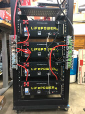
  1. For diagonal configuration of a bus bar, is it just the physical order of attachment that matter? For instance, in the attached "bus-bar-diagonal-configuration" image, I wanted to have my final cable to connect at the top (for ease of connecting to the 6000XP), so for my negative side, I just reversed the order of cables when connecting it to the bus bar (please note, that red cable on right will be swapped with black when it comes in). I assume this approach should work, but would love to confirm with the experts here.
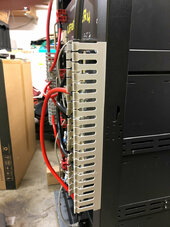
  2. On the bus bar mounting, I purchased this from Signature Solar (600A 12 stub busbar) and it actually came with mounting brackets that might have been aluminum. To mount this a bit easier to my server rack, I decided to remove the brackets and just mount it directly on the server rack itself (see attached "bus-bar-mounting" image). My big question here is... is this safe? I don't fully understand what is needed for a safe bus bar mount considering a lot of the other smaller bus bars appear to be mounted with plastic (ie, is there any logic that you need to have something non-conductive between the bus bar at the rack?)
Thank you.
 

Attachments

  • bus-bar-diagonal-configuration.jpg
    bus-bar-diagonal-configuration.jpg
    221 KB · Views: 25
  • bus-bar-mounting.jpg
    bus-bar-mounting.jpg
    157.9 KB · Views: 23
(ie, is there any logic that you need to have something non-conductive between the bus bar at the rack?)
Thank you.
Don't know about your busbar in particular, but yes there is a reason to have something non-conductive between the busbar and the rack. You don't want the rack energized by either busbar. If energized by both, the rack will short the red and black.

The wiring will work. Normally you have short wires from battery to busbar. Then connect the inverter to opposite ends of the busbar. In your setup the top and bottom batteries have long circuit paths. The middle batteries may have slightly shorter total path length. Hard to tell without measuring it.
 
The wiring will work. Normally you have short wires from battery to busbar. Then connect the inverter to opposite ends of the busbar. In your setup the top and bottom batteries have long circuit paths. The middle batteries may have slightly shorter total path length. Hard to tell without measuring it.

Oh interesting. Does that mean the length of wire between the battery and busbar also informs the order in which devices connected to the busbar are used?

I'm currently using 1 ft and 2 ft length wires on my Black side.
  • Battery 1 (top): Is using 2 ft wire
  • Battery 2: Is using 1 ft wire
  • Battery 3: Is using 1 ft wire
  • Battery 4 (bottom): Is using 2ft wire
Originally I assumed this meant the "order of usage" on that bus bar (if I connect the main cable at the top, as shown in the image), is 4, 3, 2, and 1.

But if the length of wire between battery to bus bar does matter, I assume maybe batteries 2 and 3 are used "sooner" given their shorter length.
 
Your wire between the batteries and bus bars should be the same length and size so the are the same resistance.
Note - this means the total length from battery 1 should be the same total length for the other batteries. It doesn't mean the positive and negative cables need to be the same length, just that all match total length. So measure your longest connection to the negative, and your longest connection for the positive. When added that is your total length.

The diagonal wiring means the negative bus bar is connected so the batteries on it are reverse of the positive bus bar. So connecting in exactly the reverse order will do that for you.

The bus bars should absolutely be insulated from the racking. There should be some rubber stand offs. And insulated brackets.

I can't tell from the pictures but it looks like your negative bar is green colored? What are the bars made out of? Ideally they should be pure copper that can optionally be plated in nickle or tin. If that green color is between the lugs and the bars you need to make sure it isn't going to cause a high resistance connection. Like if the bars are aluminum and that is anodized it would need to be sanded down where the lugs attach. And pretty much if they are anything but copper I would meassure the cross section and see if they can carry your target current.


Once you have the racking in place you should run a ground between it and the inverter case. Basically a single source of ground for the whole install. And realize the word 'ground' doesn't mean negative from the battery or PV panels.

Optional brain bending. Your bars have 12 lugs offset. Put each battery cable on consecutive inside lugs. Now, put the positive uplink on the lug between the connection from battery 1 & 2 on the outside. Put the negative uplink on the outside lug between battery 3 & 4. That will achive a near perfect balance where putting the uplinks on the end ina Z pattern will leave the two middle batteries slightly less used than the two end batteries. Advanced reading below to explain it.

 
Last edited:
Back
Top