diy solar

diy solar

DALY BMS 200A

ScoTTyBEEE

New Member
Joined
Sep 23, 2019
Messages
112
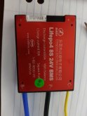
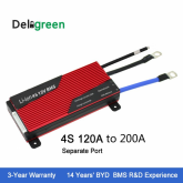
I just recently purchased the DALY 200A BMS separate port. My thinking was I need to pull around 140a maximum for an induction cooker, so this is suitable. I bought the separate port so that the charging side wasn't disconnected leaving the mppt disconnected from the batteries in an event where the load side had a problem.

I've further read the really crap information about these BMS's and it seems the 200A separate port has an 8A charging port, which is waaaay too low to be useful for anybody as a single system.

With this in mind, and the fact it's already in the mail, would it make sense to purchase a 60A common port and use this for the charging side, and continue to use the 200A for the load side. I can't see any real issues here and I may get the advantage from the 35ma balancing current being doubled to 70ma if both bms's can operate together.

Essentially I'll have the large bms handling all situations of low voltage and the smaller one handling the top end. Also being completely separate it will resolve any issues of the mppt being disconnected during under voltage protect.
 
I'm running two DALY 60 Amp units for a total of 120 amps. I think it will work just fine that way.
 
Now I've thought about it a little more the problem I can see is both bms's will see the low voltage situation and disconnect at the same time. I don't think this is going to be any different from just having one large common port.
 
I just recently purchased the DALY 200A BMS separate port. My thinking was I need to pull around 140a maximum for an induction cooker, so this is suitable. I bought the separate port so that the charging side wasn't disconnected leaving the mppt disconnected from the batteries in an event where the load side had a problem.

I've further read the really crap information about these BMS's and it seems the 200A separate port has an 8A charging port, which is waaaay too low to be useful for anybody as a single system.

With this in mind, and the fact it's already in the mail, would it make sense to purchase a 60A common port and use this for the charging side, and continue to use the 200A for the load side. I can't see any real issues here and I may get the advantage from the 35ma balancing current being doubled to 70ma if both bms's can operate together.

Essentially I'll have the large bms handling all situations of low voltage and the smaller one handling the top end. Also being completely separate it will resolve any issues of the mppt being disconnected during under voltage protect.
I feel your pain. Bought the 100 amp seperate port and it does 20 amp charging.?
I never thought about getting another common for charging but I like it. However, the comment about "seeing" the low voltage and disconnecting I think might be an issue.
 
It could be, there’s no way of knowing without testing really. It’s all in the mail but won’t be here for a month for me to report my findings.
 
Not doubting, just checking. You said that the separate charge port is rated to 8amp which seems soo very light weight even for a 60amp discharge BMS. Are you sure you didn't misread 80amp charge which would be more inline with a 200amp discharge BMS. I think the use of a seperate port BMS is to help protect the battery. Just because the battery might be rated for 1C or better discharge it's not always the case for charge. Just M.H.O. (My Humble Opinion) (y)BMS 60amp dis 10 amp charge.jpg
 
It's in the mail, so can't confirm but the specs on the advert seem to confirm it, and there are various pics too.

1569930951362.png
 
You could shoot off and email to your supplier just to check/clarify and yes they have a tendency to use generic not too descript photos in there ads but all that said I seriously wouldn't worry too much at this time. I would be gob-smacked if that unit only charged at 8 amps. I'd bet pennys to pounds (that's odds of 240/1) that it will be 80 amp and just a type O in there specs on the add, which should do you verywell. Don't worry until you have something to worry about ;):cool:
 
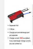
Yeah, now their advert is saying 50A charge port haha. Who bloody knows, annoyingly I bought a 60A b2b charger!! argh.

1569933588296.png
 
Arrived today and it does say 50A charge current, so fortunately I can use it for my charge controller but need a second smaller bms for my b2b charger, or I might just not use a bms on that as I can select custom charge profiles and just keep the volts nearer 14.1/14.2 and I won't need any overvoltage protection.

1570189726716.png
 
What gauge wire comes on that for the discharge port and charge port? I am VERY curious if you can actually push 200A though it and for how long. Can you test that?
 
I have the DALY 200A SP BMS installed on my system and it is not limited to 8A on the charge port.

I have an issue that I will have to trouble shoot on Monday: When I enable my 2000w Magnum inverter (after it has been off for a while) the DC power winks out! Turn it on again after the system comes back up and things work properly. I believe that the caps charging in the inverter are seen as an overload by the BMS which has a 9ms overload trip response. If this is the issue I’ll have to change out the DALY for some other BMS.

The AWG 6 wire coming out of this BMS does not make sense to me. I wanted to check these under full inverter load to see how much they heat up. I have them trimmed as short as possible. Might be another reason to change to a different BMS or use it to control a relay.

Could you run the inverter through the 220A Victron battery protect instead?
 
I have the DALY 200A SP BMS installed on my system and it is not limited to 8A on the charge port.

I have an issue that I will have to trouble shoot on Monday: When I enable my 2000w Magnum inverter (after it has been off for a while) the DC power winks out! Turn it on again after the system comes back up and things work properly. I believe that the caps charging in the inverter are seen as an overload by the BMS which has a 9ms overload trip response. If this is the issue I’ll have to change out the DALY for some other BMS.

The AWG 6 wire coming out of this BMS does not make sense to me. I wanted to check these under full inverter load to see how much they heat up. I have them trimmed as short as possible. Might be another reason to change to a different BMS or use it to control a relay.
ambient., have the inverter connected to a charge circuit with a resistor in it. Turn THAT on first, then turn on the other feeder on.
 
I have a 16S 48V Daly 200A with 30A separate port. But it seems to accept up to 40A without issues. However, the mosfets can get damaged any time, may be I have just good luck.

When my Daly turns off the output my charge port is not usable too. I expected I could further charge but I can't. In my case my MPPT chargers lose their ground reference since the batt minus is interrupted, the output rises to the same voltage as the PV: 120V. I had a few buck convertors at 55V and they all damaged everytime the BMS switched off.

I don't see any benefits from a separate charge port anymore , it's just limiting the charge current.

The 35mA balance circuitry inside does not help at all for my 200A cells. I see from my cell data logger that some cells discharged to 2.4V before BMS turned off. I don't trust it at all.

The Daly is sealed and there is no good reason to make a BMS completely waterproof. It's always near the batteries and we don't put them in the rain, do we? As usual with crap they don't like you to look inside.
 
Last edited:
@ScoTTyBEEE
At first sight, I don't think using 2 BMS for handling Low and High end will work.
A BMS turns on/off depending on individual cell voltages. When discharging and one cells goes under 2.5V both BMS will interrupt B-.
So you will not be able to charge.
At the high end , same will happen. If one cell exceeds 3.65V both BMS will turn off again disconnecting ground from your chargers again.

Because we usually don't have access to BMS parameters and no monitoring, I made my own BMS and I turn off at any setting; now 2.8V / 3.5V. I disconnect the + terminal to the load and I am still able to charge. If overcharged I disconnect the PV inputs to the MPPT controllers one by one depending on the load. By monitoring current from several identical PV groups I can detect shadowing and protect my panels by switching off the shaded group. My BMS is only a last resort if mine should not wok.
 
Last edited:
Yes I agree. I tested a daly bms yesterday and I think this 35ma balancing is far too low to handle the top of the charge. I think a better solution is the active cell balancer on ali which can handle up to 6A and the victron low voltage disconnect, maybe keeping the chargers max limited to 14.0-14.2v. This also means you can run decent cables for 2000w inverters rather than having to use the frankly underspec'd cables on the bms.
 
Back
Top