diy solar

diy solar

Debunk: Alternator DC to DC charger not required for big Lithium Battery

Totally makes more sense now.

1. I ran a couple pairs of cables all the way to the front so the sense voltage was at the lynx distributor right by the batteries 40ft. Same with the shunt wires.

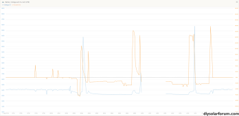
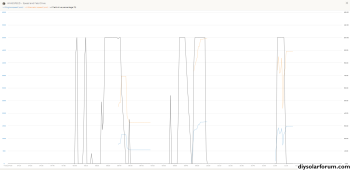
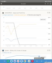
2. I changed some settings for the profile and such to match how I wanted to charge. Also set a limit of 250a then down to 200a. Went through every setting and all is right, only thing was I never got the pulley size right so the rpm was off but didn't use that. Just used a 1 min delay before turning on

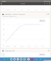
3. I don't. I love the wakespeed and it integrates with Victron so I could watch how much it's working and my alt temps. But my alt is 24v and batteries are 12v and 48v separate systems. I should swap my 12v quattro for a 24v one and just use a 24/12 Orion for 12v loads since it's just lights and electronics... or just use 120v to 12v as I also have this setup as a backup. My battery bms's are fried I think so can get a 24v bms.

I did buy a 24v regulator for my 50dn alt so I could get rid of the wakespeed.

I think I could use the wakespeed as a 12v and just connect my 12v generator battery so it'll help absorb any spikes... as it's also a separate system. But 12v would be half the watts through the 2/0.

Another option I've been thinking is a 48v 100a balmar and have a 3rd alt as I have a bracket for it and room. But it's 3k and I don't need that much power. 2kw for my main 48v system and 2kw for the aux 12v system is plenty.
1. were the shunt extension wires a twisted pair or shielded wire with a ground on one end? That length you can get a big emf error.

2. You do not really need rpm and it does not need to be accurate any way. that is mainly there so that you can depower the alternator on small engines so that you have the power needed for propulsion. On my boat, I have a 21hp diesel and if I am swinging a 160A alternator, it will kill the engine at idle and would overload the engine at max cruising speed. In my case, the whitespace is a big deal.

3. I am not sure about the 24 vs 12 issue. I believe that it could work as you intend because there is nothing in an alternator that sets the voltage output other than the regulator. Even it does not tell the alternator to "make 14.4v". It tells the alternator to make power [watts] and the resistance that it runs into determines the volts. P=I^2 x r. or P = V x I. Once the regulator is happy with the voltage it sees at the sense wires, it reduces the field current which lowers the power output to maintain that voltage. The old Chevy DN10 alternators were used on 6v, 8v, 12v, & 24v systems and the only thing that changed was the regulator. You can also take a standard 10SI automotive alternator and boost its output to 16v by installing a small resistor on the excite wire.

4. the WS500 will work on 12, 24, 36v & 48, systems.
1. Nope it was just speaker type wire pairs. 12 or 14 gauge in pvc conduit with other wiring.
2. I didn't see a need to configure it so guessed the sizes and was off. I have a Detroit Diesel 60 12.7 so hp isn't an issue.
3. I can just see the wakespeed ramping down the field from 100 when temps are over 200F (oil cooled and oil temps are 200F but didnt adjust it yet) so it was pumping 12v with field 100%. I don't know how it uses the field to control voltage but my bet is its not able to hold it down the entire time and skipped a bit. I think having a lead acid inline would absorb the spikes unlike lfp which apparently blows the bms if too large
1. It is recommended that the shunt wires and to a lesser degree the sense wires be twisted pairs especially on long runs.
2. That is what I figured.
3. You can change the temp settings in the app so that is easy to get around. The regulator does not "control voltage". It controls how much current it sends to the field windings with a PWM wave form. It can be adjusted from 0 to 100%. At 0% the alternator will put out no power so charging will stop, and the battery voltage will be at a resting level and the alternator will be the same. At 100% field, the alternator will put out the max power in watts that it can give at the level of the battery voltage and the rpms of the alternator.

This must be on a boat because your system keeps getting more involved. At first, we were talking about 12v and then it had 12v and 24v and then up pops 48v. You really need a highly skilled marine electrician to set up the whole system to work in harmony.

What part of the world are you in? I know a guy in BC Canada that could get it all sorted.
 
1. It is recommended that the shunt wires and to a lesser degree the sense wires be twisted pairs especially on long runs.
2. That is what I figured.
3. You can change the temp settings in the app so that is easy to get around. The regulator does not "control voltage". It controls how much current it sends to the field windings with a PWM wave form. It can be adjusted from 0 to 100%. At 0% the alternator will put out no power so charging will stop, and the battery voltage will be at a resting level and the alternator will be the same. At 100% field, the alternator will put out the max power in watts that it can give at the level of the battery voltage and the rpms of the alternator.

This must be on a boat because your system keeps getting more involved. At first, we were talking about 12v and then it had 12v and 24v and then up pops 48v. You really need a highly skilled marine electrician to set up the whole system to work in harmony.

What part of the world are you in? I know a guy in BC canada that could get it all sorted.
It's a Prevost coach RV. I custom built the electronics all Victron. Wanted the 48v but also a redundant system just incase and already had the 12v from my old rv. 10kw batteries for each but will be 20+ on 48v. It all works great and separately just want to integrate the alternator for charging while driving on top of the solar. Thing is severely overbuilt with massive electrical outlets so perfect for rebuilding into a complete redundant system.

I figured it's pwm controlling the field voltage and that's why I figured it's timings off and tweaks a setting which unleashes way over 14v for a split second. I figured the DC to dc converters are best so I can split to both banks. I'm wondering if I should adjust the DC to dc converters voltage so each one is a bit lower than the other, especially with the 8.5a 48v ones since I have 4 of them. I really don't need much power during the winter as solar should keep me topped off, it's the AC that is needed.

Planning a boat build in a couple years just haven't found the right vessel
The PWM control to the field is controlling the magnetic field which is not an instantaneous change. More of growth and decay so if you look at the voltage on an oscilloscope it will have a reasonably smooth voltage.

Are your batteries sealed case with or without Bluetooth or DIY? It sounds to me like your spikes could be a BMS disconnect which it not friendly to an alternator or BMS. Do you have anything to control voltage spikes in the case of a BMS turning off the batteries?
They're 2x400ah EG4 12v batteries.

Here's what it looked like when everything happened. It always shows the field at 100% but it could be not the actual signal its sending just that its not derating the field for xyz reason. I don't think the BMS was the issue as when they trip i need to reset it manually. Now they're stuck with an alm light but working so my bet is the BMS is fried when the spike hit. I already had the batteries replaced under warranty when i didn't know what happened the 1st time but now i know its my fault I'm not getting them replaced under warranty.
 

Attachments

  • shunt.PNG
    shunt.PNG
    93.5 KB · Views: 4
  • s1.PNG
    s1.PNG
    73.7 KB · Views: 4
Well, i don't think the system is operating correctly if the field is 100% for long periods unless your large battery bank was at a low voltage, and if that WERE to occur you should be able to see the alternator temp increasing during those load periods as well as a perceptible bump in voltage when the field goes to 100%.

But while you SAY the field is "always" at 100%, the graph you posted suggests otherwise. Was the engine off during the periods that the graph shows 0% field? If the engine was running during that entire graph, then it doesn't make sense!

Can you pick which data points you can graph together? It would be good to correlate field% to voltage, current, and temp. That should show a pretty predictable relationship and might shed light on why the field duty cycle would change in such an immediate/extreme way during your 'fault' condition.

I read through a couple of the documents for the WS500 and noted a few things which MAY be relevant to diagnosing this:
  • "New user defined Max Battery voltage fault threshold MaxBatVolts ($CPB: command)"
  • "Promiscuous Mode” ($SCO: command) – allows auto restart on almost all detected faults. "
  • "New ability o set battery specific max system voltage for hard fault. Referance $CPB command page 43 "
Also:
1697829180286.png
1697829223429.png
I am surprised by how many spelling errors appear in the documents for such a complicated device. ?

But it seems like you can experiment with putting a cap on the field duty cycle % which may prevent your voltage spikes as a bandaid, although it doesn't really address the root cause of them. Even if you do not want to get in and start altering these field values, there is a DIP switch on the housing which applies a derate of the field to 75%, which may or may not 'fix' the problem but MIGHT give a measurable change in the symptom, at least letting you know whether derating the max field strength would address the spike symptom or not.

1697829670835.png
1697829690847.png

I think derating your max field percentage SHOULD stop the symptom until you can determine the root cause of the 100% field duty cycle behavior.
 
Last edited:
Well, i don't think the system is operating correctly if the field is 100% for long periods unless your large battery bank was at a low voltage, and if that WERE to occur you should be able to see the alternator temp increasing during those load periods as well as a perceptible bump in voltage when the field goes to 100%.

But while you SAY the field is "always" at 100%, the graph you posted suggests otherwise. Was the engine off during the periods that the graph shows 0% field? If the engine was running during that entire graph, then it doesn't make sense!

Can you pick which data points you can graph together? It would be good to correlate field% to voltage, current, and temp. That should show a pretty predictable relationship and might shed light on why the field duty cycle would change in such an immediate/extreme way during your 'fault' condition.

I read through a couple of the documents for the WS500 and noted a few things which MAY be relevant to diagnosing this:
  • "New user defined Max Battery voltage fault threshold MaxBatVolts ($CPB: command)"
  • "Promiscuous Mode” ($SCO: command) – allows auto restart on almost all detected faults. "
  • "New ability o set battery specific max system voltage for hard fault. Referance $CPB command page 43 "
Also:
View attachment 173257
View attachment 173258
I am surprised by how many spelling errors appear in the documents for such a complicated device. ?

But it seems like you can experiment with putting a cap on the field duty cycle % which may prevent your voltage spikes as a bandaid, although it doesn't really address the root cause of them. Even if you do not want to get in and start altering these field values, there is a DIP switch on the housing which applies a derate of the field to 75%, which may or may not 'fix' the problem but MIGHT give a measurable change in the symptom, at least letting you know whether derating the max field strength would address the spike symptom or not.

View attachment 173259
View attachment 173260

I think derating your max field percentage SHOULD stop the symptom until you can determine the root cause of the 100% field duty cycle behavior.
Only the spots where the other lines are on is when the engine is running and I have a 2 minute delay before the alt turns on. I zoomed in where it blew everything. I show the field is at 100% before I've seen it derate the field when it's alt temp sensor get above 200 but since the alternator is oil cooled it warms up with the engine which is right around 200 and doesn't really get hotter. If working normally I'd increase this to 210 or so.

I found those options too when I was working on this but the windows software isn't built by wakespeed but some offgrid company and doesn't have these options, plus it trips the high voltage limit when it spikes and it's not fast enough to shut the load.

I'm going to use dc to dc converters and connect everything to the chassis 24v batteries then disable the chassis alt with a switch. This way I use 24v and double the wattage through the cable and convert it.
 

Attachments

  • Screenshot_20231020_153504_VRM.jpg
    Screenshot_20231020_153504_VRM.jpg
    181.4 KB · Views: 3
  • Screenshot_20231020_153448_VRM.jpg
    Screenshot_20231020_153448_VRM.jpg
    250.3 KB · Views: 3
  • Screenshot_20231020_153426_VRM.jpg
    Screenshot_20231020_153426_VRM.jpg
    234.5 KB · Views: 3
  • Screenshot_20231020_153418_VRM.jpg
    Screenshot_20231020_153418_VRM.jpg
    204.3 KB · Views: 3
Yeah, i mean there's definitely multiple ways to address the voltage spike but simply using it as a 24v system with a step down converter to 12v somewhere else, is probably the 'easy button' vs diagnosing the internal logic of this controller. Can't blame you.
 
I'm not fully caught up, but that kind of behavior is 100% consistent with an imbalanced battery triggering BMS overvoltage protection due to a single cell hitting cut off. The load is instantaneously removed from the incoming voltage and current, and the charger can't clamp down on it fast enough, so voltage spikes.
 
Hey all, came across this thread as I currently have a split relay feeding 3x85ah lead acid batteries (also have 300w solar panels fed into a MTTP controller)... im about to buy a single 100ah LiFePO4 battery and wondering if I will be fine dropping it in with the current split relay?

My vehicle is a 2009 Vauxhall Movano - Alternator rating - 150a / 14v

Am I likely to be fine with this or do I really need to shell out on a DC to DC?

Many thanks

Hi @goblin00

Short answer “no” it isn’t ok ,,, it might work, but you could be stressing out your alternator.

Longer answer is you would have to go thru the minutia of detail with all your equipment & wiring & vehicle ,,, etc to analyze your proposal. Example 150a rated alternator 🤔 ,,, what does that mean? Are you gonna charge @ 1500rpm? ,,, What power does the Vauxhall use? ,,, what kind of condition is your starter battery in ? ,,, etc etc

I use to “direct charge” my AGMs, but I monitored it & used the internal resistance at higher SOC to moderate the current. When we altered our use pattern I purchased a Kisae 1250 to limit the current to 50amps. The Kisae is also user programmable ( 5amps to 50amps ) & charging parameters like voltage, so you can dial in your batteries.


It also is a MPPT Solar Charger 😁.


On Another Sad Note, I came across this last night ,,, the guy lost his van;


IMG_9301.jpeg
IMG_9300.jpeg

Suspecting the MPPT 😳.
 
Last edited:
Not going to bother with the whole video but given that it's in an RV, it's almost a certainty that the wiring to the LFP battery is as worthless as it is in most RVs including the five I've owned.

LFP take on maximum current for the vast majority of their charge and do so under 13.8V. This can exceed the duty cycle of a typical alternator as they must achieve absorption voltage before current begins to taper.

There is always substantial voltage drop due to wire gauge/length between alternator and coach battery ESPECIALLY at 12V.

The voltage drop causes the alternator to "see" a higher voltage than is present at the battery terminals, thus it will begin to taper current. It's not uncommon to see voltage that the battery to be 0.6V below the alternator output voltage.

Some alternators also regulate their own output based on temperature and will protect themselves.

If one can verify that the current is within acceptable limits, one can charge directly from alternator.

For smaller installations where there is not excessive voltage drop, a DC-DC may become necessary.

This video seems to go against the current state of advice regarding using the alternator to charge lithium directly. I haven't seen this discussed here (maybe I can't find it) @Will Prowse is recommending a Renogy DC-DC convertor for RV charging LFP from the alternator.

Does this guy know what he is talking about?
I charge my 300Ah Lithium directly for the alternator with out any problems DC-DC charging is almost more needed to increase the power draw. I added an extra separator rele just to manage to gett 40A from the alternator that's 2x6mm2 and I have a short distance between the batteries and power tapers off at the top, I have never tried to go all the way down to 12V with the lithium that is something to think about put it has 2x40A braker så in worst case it will shut down, it delivers 13,8V 3,45v per cell and that is plenty to get to 99% with some absorption time. I imagene that they alternator never manages to see the full demand from the lithium due to the voltage drop from/to the rv batteri

Off course all new cars at least in Europe have a smart alternator and with those you need to use DC-DC charger just to get any charge and originally most come with a tiny 10-20A one and the ones that don't see 1-5A charging at most.

Cable size, voltage drop and heat is absolutely a problem with DC-DC converters just as it is with out
 
Yep.


Of course. A 250A alternator @ 14.4V is going to have a wicked voltage drop. 20' run of 2awg 14.4V/250A will have a ... 1.56V drop, so the alternator will almost never output 250A to the battery thus ensuring the alternator is never stressed. I would be surprised if output current is ever much over 100A.

Please note:


If one's installation is running an alternator at near capacity, it's likely not going to work, unless the alternator can regulate its output based on temperature. Not all do.


As an absolute statement, I can't agree. I assume you are not aware that LFP can be nearly (95%+) fully charged at 13.6V and fully charged at 13.8V? Most will charge to these levels; however, the voltage drop issue is the actual cause of failing to achieve full charge.
the voltige drop disappears as the current drops so eventually you will see 13,8V and with some absorption time it will fully charge.
 
I have a 1/2 ton truck which has a 270-amp alternator and is rated 170 amp at idle. I added a fused wires(dedicated ground wire) from the battery of the truck to an Anderson connector at the back of my truck and ran additional wiring to a Victron 360-watt DC-DC converter mounted in my RV. The wire is high quality 6 gauge. I have used this set up on many trips and have had no issues and am able to charge my LiFePO4 batteries to 14.4 volts. I added this since many of the places where I camp have lots of trees or are in deep canyons and have inconsistent light to charge from solar. I charge when moving from site to site or in an emergency I can run my truck and charge. I disconnect the connector when the truck is not running. The converter does get warm, but I mounted it vertically to improve airflow across the heat sink. I have been very happy with this set up. I have a small trailer, so weight is a limiting factor, so a heavy battery and solar panel load is not an option. However, I would not do this unless you have a large, high-capacity alternator, so for most vehicles it may not be a good option as mentioned in other posts here.
There is a difference with a car and trailer compared to a coach, with 6m+ cabling you need the DC-DC to be able to boost opp the voltage to get a charge.
 
Just to confirm do you have any lead acid batteries in this system?

I'm confused about a couple things. Is the voltage drop from wire length limiting the batteries ability to pull current or is it simply the wire size limiting the current? If it's the wire size isn't it getting severely hot?

If it's the wire length and voltage limiting the current it seems like your entire system is relying on the alternators regulator to be at that specific voltage. If this failed and voltage ramped up even a little it could cause all kinds of issues.

I was under the assumption that lfp pulls all the power it has available at all times until it's full.
There is a lead acid batteri in parallel yes. that in it self is never a problem as the voltage of a lead battery is lower than the lithium and drops way down when the lithium starts pulling on it.

Not that simple the alternator supplies constant voltage and the drop in voltage to the lithium means that the higher the draw the bigger the voltage drop is so it self regulates to a point and it is not getting any hotter then if you are running a DC-DC charger as it will pull the same power with the same voltage dropp to the DC-DC

The line is fused of course and the BMS will protect the lithium, worst for the led battery that will get cooked.

The lithium needs voltage to be high to be able to pull max power this is the same when people limit there solar to a low boost charge, it slows down the charge and takes longer to fill up.
 
Hey all, came across this thread as I currently have a split relay feeding 3x85ah lead acid batteries (also have 300w solar panels fed into a MTTP controller)... im about to buy a single 100ah LiFePO4 battery and wondering if I will be fine dropping it in with the current split relay?

My vehicle is a 2009 Vauxhall Movano - Alternator rating - 150a / 14v

Am I likely to be fine with this or do I really need to shell out on a DC to DC?

Many thanks
I would say it should be fine just measure what you are getting now and make sure the line is fused then just monitor if its similar to the old system just go down to 10% charge to see how much it draws.
 
Hi @goblin00

Short answer “no” it isn’t ok ,,, it might work, but you could be stressing out your alternator.

Longer answer is you would have to go thru the minutia of detail with all your equipment & wiring & vehicle ,,, etc to analyze your proposal. Example 150a rated alternator 🤔 ,,, what does that mean? Are you gonna charge @ 1500rpm? ,,, What power does the Vauxhall use? ,,, what kind of condition is your starter battery in ? ,,, etc etc

I use to “direct charge” my AGMs, but I monitored it & used the internal resistance at higher SOC to moderate the current. When we altered our use pattern I purchased a Kisae 1250 to limit the current to 50amps. The Kisae is also user programmable ( 5amps to 50amps ) & charging parameters like voltage, so you can dial in your batteries.


It also is a MPPT Solar Charger 😁.


On Another Sad Note, I came across this last night ,,, the guy lost his van;


View attachment 219577
View attachment 219578

Suspecting the MPPT 😳.
looks like a solar panel fire
 
Hey all, came across this thread as I currently have a split relay feeding 3x85ah lead acid batteries (also have 300w solar panels fed into a MTTP controller)... im about to buy a single 100ah LiFePO4 battery and wondering if I will be fine dropping it in with the current split relay?

My vehicle is a 2009 Vauxhall Movano - Alternator rating - 150a / 14v

Am I likely to be fine with this or do I really need to shell out on a DC to DC?

Many thanks
Put maybe 30 amp fuse in the line (assuming #10 or better wire) and see how it goes. If the fuse opens.... replace it with a 20 amp DC-DC charger.
 
Back
Top