diy solar

diy solar

Deye (Sol Ark) battery relocation and re-cabling since first installation

LydMekk

Call me Icarus
Joined
Apr 9, 2022
Messages
905
Location
Spain
So since my first installation in spring of 2022 with 3 pcs. Growatt SPF-5000 ES and premade batteries with 35mm2 DC cables the system has been enlarged in several steps. This is a 3-phase setup.
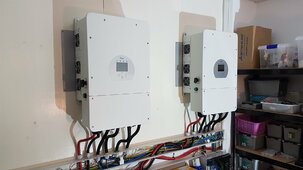
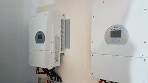
Firstly as the Growatts (5kw each) started taking each other out with fires and literal explosions inside from 28.12.22 they were replaced with Deye (Sol Ark) 8kWs 3 pieces. Same 3-phase setup.

Also in spring of 2023 I expanded the battery bank with 2 more 15S 280AH batteries. So now running 1360AH total in 6 batteries.

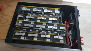
Was made aware of issues from other manufacturers of placing the premade batteries pointing straight up instead of flat mounted. This makes the cells lying flat and a possibility of leaking fluid from the valves. The MfG was the one saying the packs should point upwards...
I agree that it is always a good idea with a battery to have the valves point up. This is 4 pcs. of a big 200AH battery type.

Pictures:
20220709_103314.jpg

20220709_153706.jpg

So looked into what was available in 19" rack system that could be used for this. Not much available used here.
And the ones solid enough to take the weight was expensive.
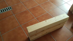
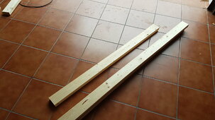
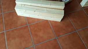
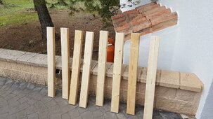
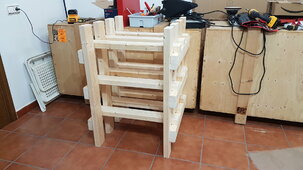
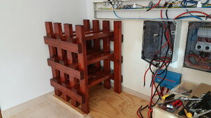
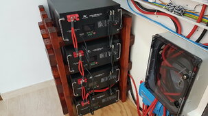
So, wood it is. 2x4 technology at its finest ^^ :cool:

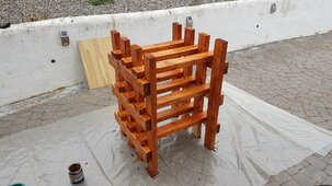
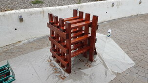
Making the wood rack:

20240129_114125.jpg

20240129_114134.jpg

20240129_114140.jpg

20240129_114154.jpg

20240129_114159.jpg

20240129_172256.jpg
 
As this is to be placed indoors wood treatment isn't very necessary but I like the idea of adding some wood stain (lasur) to it. Will give it 2 layers tomorrow. The wood will carry 270kg of the upper 3 batteries. The first one will be on the floor on a wood plate.

The next step will be to reconfigure the DC battery cabling. As I started with both a lot less battery capacity and smaller inverters the time has now come to upgrade (hopefully for the last time) the size and routing of the cables.
Going from 35mm2 to 95mm2 from each of the inverters to the busbars and also from 35 to 70mm2 from each battery to the busbar.

The 35s are getting lightly warm when charging and/or supplying bigger loads, not much but around 40-45c I guess.
Want to lower the resistance so going with 70mm2 which is rated up to 200AH per battery.

And to please the Blue crowd (TM) and @Sunshineeggo ... there will be a couple of Victron Power-In busbars interconnected in the center of the wall.
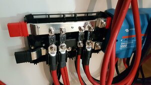
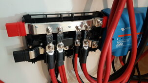
Got one from before and another is in the mail. Rebuilding each to take 250A 58V Mega fuses on every connection.

Mega Fuses 58V 250A

Link to the eXoda cable lug supplier in Germany, very nice thick plugs in plated copper. Have used them before and highly recommended. Miles above the standard shitty ebay and amazon cheap stuff.

eXoda cable lugs

OCC fine thread copper cables from (also used these before very good quality):

https://www.amazon.es/gp/product/B0812DDSM4/ref=ppx_yo_dt_b_asin_title_o01_s00?ie=UTF8&th=1

Everything is ordered and en route.

Also my 2 EG4 Chargeverters will be connected to the same double busbar.

According to Victrons written document reg. all matters cabling etc. they recommend going like this, starting from left (in a multi inverter environment):

Inverter - Battery - Charger - Inverter - Battery - Charger - Inverter - Battery

This to make sure the load on each component is as balanced as possible.

This is an home installation where we normally do not use a very high load. In winter we stay around 4-6kW as a daily average at all times. The normal max I've seen on the stats is 11kW regd. draw. The max of the system is 24Kw.

But with charging going on during daytime with another 180AH max. (I put in a limit) at the same time there is some "traffic" on the cabling and the system.

This upgrade is make sure there will be no more heat on the cables and future proof it all.
Also to make sure the load is spread out more evenly in regards to pulling from all batteries etc.
 
Last edited:
Can I ask why you picked the 15s config batteries? Are they much cheaper per kWh? Or just what was available?
 
The 4 of them with which I started the system back in 2022 was what was available at the time from within the EU.
This was back in Cuff time and availability was shait.
 
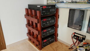
Progress today. Removed the batteries. Modded the floor plate a little and got the 2x4 rack situated.
Moved the 4 pcs. of 90kg (each) batteries in it. That was a BEAR of a job. Doesn't help that i is not much space around the rack as it sits in a corner. But, got it sorted in the end.

20240205_115949.jpg

20240205_142247.jpg
 
Last edited:
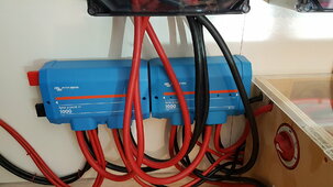
Removed all the old 35mm2 cabling today. Measured and cut the 95mm2 cables for the inverters down to the Victron busbar.
All 3 sets are exactly the same mm lengths ^^. I do love splitting my millimeters LOL :LOL:
Tomorrow will be crimping on the 95mm plugs.
Will also be putting on new 70mm2 battery cables on the 3 sets of batteries. Paying attention the exact same lengths there.
The older black premades are a little tricky when it comes to the size of the cable terminals and the short cables from terminal to each terminal. I do not want to start grinding away on the plastic on the terminals.
Can not go over M8-35mm2 cable lugs. BUT, I will be able to double up on those cables. They are only like 30cm each so not much lengths anyway. Pictures of that tomorrow.

Mounted the extra Victron Power-In to the left of the old one. Yay, I doubled my Victron collection ^^ ;)
 
So since my first installation in spring of 2022 with 3 pcs. Growatt SPF-5000 ES and premade batteries with 35mm2 DC cables the system has been enlarged in several steps. This is a 3-phase setup.
Firstly as the Growatts (5kw each) started taking each other out with fires and literal explosions inside from 28.12.22 they were replaced with Deye (Sol Ark) 8kWs 3 pieces. Same 3-phase setup.

Also in spring of 2023 I expanded the battery bank with 2 more 15S 280AH batteries. So now running 1360AH total in 6 batteries.

Was made aware of issues from other manufacturers of placing the premade batteries pointing straight up instead of flat mounted. This makes the cells lying flat and a possibility of leaking fluid from the valves. The MfG was the one saying the packs should point upwards...
I agree that it is always a good idea with a battery to have the valves point up. This is 4 pcs. of a big 200AH battery type.

Pictures:
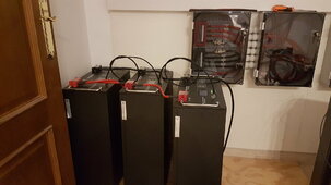
View attachment 192216

View attachment 192217

So looked into what was available in 19" rack system that could be used for this. Not much available used here.
And the ones solid enough to take the weight was expensive.
So, wood it is. 2x4 technology at its finest ^^ :cool:

Making the wood rack:
View attachment 192220

View attachment 192221

View attachment 192222

View attachment 192223

View attachment 192224

View attachment 192225

Search Alpha Passoni battery rack for sale in battery for sale section.

Don’t know if it would work for you, but it’s fireproof.
 
LIFEPO4 chemistry are NOT prone to fires. This is not an old repurposed EV car battery with high flammability.
Why would I consider whether the rack is fireproof or not?
As you can see from the pictures my 2x4 "rack" are already made and in place so I would not buy another rack for now.
 
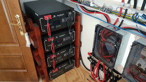
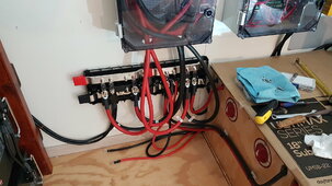
Todays work done. Finished the project. Did all battery cabling.
Installed and cabled against the 2 Victron busbars.
Everything is fused with the 58V 250A Mega fuses listed earlier.
All contact surfaces, nuts, washers etc. has been cleaned with alcohol.
All cable lugs are ofc. heatshrinked.
Torqued every connection.

Some photos:

20240208_095332.jpg

20240208_095341.jpg

20240208_095345.jpg

20240208_095350.jpg

20240208_095355.jpg

20240208_095401.jpg

20240208_145016.jpg

20240208_145017.jpg

20240208_145145.jpg

20240208_145154.jpg

20240208_145205.jpg
 
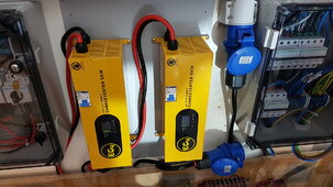
Flipped the 2 EG4 Chargeverters 90 degrees so the warm exhaust air goes straight up instead of sideways.
It will accomplish a slightly better cooling and therefore lower the chassis temp during bigger loads on them.
"Heat rises".

Atm. charging up the bank from the grid. Didn't finish before the sun was too low today. Was a shitty day weather wise.
Rain reported to commence the next 5 days...so grid charging it is ^^.
Will be nice to get all 3 batteries up to 100% first time since end of October.
Getting all BMSs to recalculate SOC again by going full and keeping them there the next day.
All this is voltage regulated. No BMS comms. Works very well for me.

No cable heat at all after this rebuild. Very pleased with the results so far.
Have also upped the charging amps from the 3 inverters to ensure better harvesting during the sunny days ^^.
Will monitor and see how the voltage regulates over all battery banks and equipment the next week.
Should be as perfect as possible with regards to the rebuild solutions chosen.

EG4s are off atm. as the inverters are directly connected to the grid for the charging. Will switch back to them to tender the pack after it goes to 100% for a couple of days.

Leaving the lids on the channels open to evaluate any need for ferrites on the new DC cables.
So far no "singing" or HF detectable with the thicker cables. Hm, maybe due to less resistance?
The AC cables already have ferrites. I hate noise...

Now come on local spring! Can't wait to meet ya! ;) :LOL: :cool:
 
Last edited:
Bought them from a retailer here in Spain.
Very happy. Been fault free for over a year now.
Got them installed last year 01. Feb. 23

HUGE upgrade from my earlier Growatts.
Those were a class A piece of crap.
The Deyes (Sol Ark) feels like an Abrams M1 tank in comparison.
Completely different league.
Highly recommended.
Pay once, cry once ^^ ...
 
The plastic box, is that just holding excess cable length? To give you slack for future equipment moves?

Also I see you have a um18. I still have four in their boxes need to build their sealed flat packs, to go with my four operational ones.
 
Yeah as I parallel 3 inverters they need to have the exact same DC cable length down to the busbars.
And the 2 on the sides needs a longer cable to reach than the center one.
So the solution is to make all 3 exactly the same...and make circles in that plastic box so they all reach the busbar with the same drop. In addition I gave them each 50cm more length just in case for any future changes.

I love my Dayton 18"s. Got 4 in my dedicated home cinema cornerloaded. 73m2 room. Also got 2 13"s.
More than enough bass. Plus I am running all my speakers full range + LFE up to 25hz.
Got the flatpacks from Parts Express. Slightly modded with stronger corners inside and polyfill ca. 20cm all around and a plastic netting in there to avoid the poly falling onto the element motor.
 
After almost 2 months now running the EG4 Chargeverters in a vertical position to let the hot air escape easier works very well.
The surface temp on the top part (or right side if horizontally - exit) of the EG4 has lowered by over 20-25 degrees C.
So absolutely worth it to mount them vertically instead or horizontally.

Btw. the heat in the room after the recabling etc. mentioned earlier in the thread has gone down around 4-5 degrees celsius due to lowered resistance and also the pure Victron copper busbars instead of a mix of copper and brass.
This is a small room roughly 14m2 in size. EDIT: to clarify this reduction in heat was before the Chargeverters were turned on.

March is a little special around here. I get some lensing I think when semi-clouded etc. but also in clear weather the production has been higher than before.
Several days I hit around 15.44kW production out of a 12.96kW system with 3x8=24 panels active atm.
The max I could reach with the old thin cables, busbars etc. was around 9.75kW.

So my conclusion is that this whole operation was very much worth it.
Will continue to monitor and report.
 
Last edited:
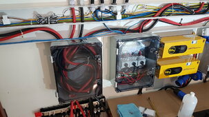
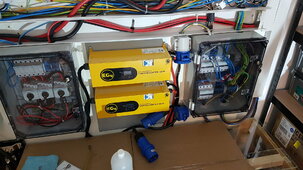
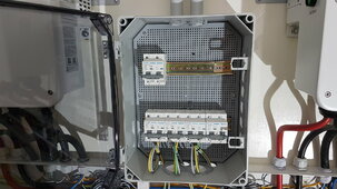
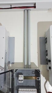
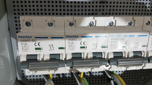
Prepping for future extra strings.
Re-using a plastic cabinet I removed to have more space on the wall for the relocation of the 4 x 200ah batteries shown earlier.

20240423_163650.jpg

20240423_163700.jpg

20240423_163720.jpg
 
Back
Top