diy solar

diy solar

DIY Solar monitoring.

I started tinkering with Raspi, Node Red, Grafana & InfluxDB using Modbus -> IP to my Midnite Classic-200 controller and I just got the latest MODBUS specs & info for my Samlex EVO-4024 Inverter (not released publicly). I posted an initial setup here at Midnite: http://midniteftp.com/forum/index.php?board=73.0 feel free to peruse and use anything handy there.

This is a "winter" project which I will be working on, once the ground is covered and I'm tired of having a frozen face. (Dang Canadian Winters !)
Do you have the classic register map?
I am a member of the MidNite Forum as well!
My controller is not a Classic, but is a MidNite product, took me several attempts to figure out it was not MODBUS... "Classic is"
 
RE: Personal solar power production record keeping and statistics

Craig; Thank you for the encouragement to tackle programming platforms.
FIVE WHOLE YEARS TO GET THIS FAR using Arduino and Pi and lots of :coffee:...

gnubie; Thank you for your help with the serial port hints.
I have found the serial problem ? !

Over the past four days I've progressed quite a ways in using Node-Red, extracting data to CSV, then opening in LibreOffice, exporting to my Windows laptop, I'm yet to play with it.
During the day I found the data was coming through very nicely until I turned on the inverter "with a particular load" I would loose and/or have incorrect data, finding the interfering load I proceeded with out that load.
During the night, the same thing with different loads? Dumping those loads.
I'm a bit peeved the ripple from the inverter with devices attached have an effect on the controllers ability to send data!!

My next move is to make a Dashboard with most of the available data.
Then have the Pi powered by the batteries, not using the AC/DC adaptor, tied it a while back and it did not like the inverter power at all.
Thanks again ;)..

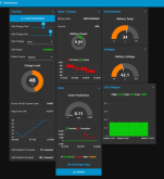
Take a look at the Node-Red dashboard pallet, you can feed it your data directly and even make functional controls from it. Here's mine

1572522482576.png

Of course if you want more than a day or two of data to review I'd suggest influx DB and Grafana

Here's my Grafana historical graphs fed off influx DB

1572522704129.png
 
Take a look at the Node-Red dashboard pallet, you can feed it your data directly and even make functional controls from it. Here's mine

View attachment 1594

Of course if you want more than a day or two of data to review I'd suggest influx DB and Grafana

Here's my Grafana historical graphs fed off influx DB

View attachment 1596

L-P-G; That will take me another 5 years to do that :cautious: ;) ...
I do like it though.

The Classic Registers are here: http://www.midnitesolar.com/pdfs/classic_register_map_Rev-C5-December-8-2013.pdf
I cannot speak to their other products, as I have a Classic-200 and that's what I worked on.

Steve_S; Yep just wondering if you had or knew about it. I did think of Classic when shopping, MODBUS scared me off "master, slave config" because it was new to me :whistle: ? The online monitoring was a bonus though.
Mine has ASCII RS232 comms, five year head ache, I'm not a coder, to get to this basic decoding stage "rewarding ?".
 
L-P-G; That will take me another 5 years to do that :cautious: ;) ...
I do like it though.


Steve_S; Yep just wondering if you had or knew about it. I did think of Classic when shopping, MODBUS scared me off "master, slave config" because it was new to me :whistle: ? The online monitoring was a bonus though.
Mine has ASCII RS232 comms, five year head ache, I'm not a coder, to get to this basic decoding stage "rewarding ?".

I actually have some stuff also running on MODBUS so if you want some code examples I can send you a couple things.
 
I actually have some stuff also running on MODBUS so if you want some code examples I can send you a couple things.
Oh that would be nice ! As I posted on the Midnite Form where my stuff is, it will be opensource & free to anyone who wants it. Unfortunately it will be at least another month before I get back to it... Fall - Winter prep (aka combat) so I will like start a posting - thread here as I think we have a broader community with more hardware etc that could be incorporated and tested by anyone interested. I like community projects, especially when it's helping folks make a better life / world for all of us.
 
Oh that would be nice ! As I posted on the Midnite Form where my stuff is, it will be opensource & free to anyone who wants it. Unfortunately it will be at least another month before I get back to it... Fall - Winter prep (aka combat) so I will like start a posting - thread here as I think we have a broader community with more hardware etc that could be incorporated and tested by anyone interested. I like community projects, especially when it's helping folks make a better life / world for all of us.

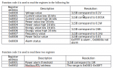
Here's a sample flow I use with a PZEM-016.


and here's the registers from the manual of the PZEM-016 so you can cross reference what goes where on the flow to the manual.

1572531908339.png

If you have the registers for your midnight I may be able to cook something up.
 
WOw nice dashboard. personally I know nothing of node red but it looks like I will have to learn.


So here is what I have been able to do so far.

I tried using an ADC connected to a shunt and 2 voltage dividers to measure power drop across shunt and it kind of worked but it was not very accurate seemed to bounce around quite a bit.

So I had about 20 of these CJMCU-226 laying around. they will measure current and voltage up to 36 volts the onboard shunt will measure current but not that much maybe 5 amps and send it to RasPI through i2c interface.

Problem is 5A isn't going to get me very far. So i removed the tiny shunt mounted to the board and hooked up the in+ and in- to my 200A shunt.
this worked but the values reported by the adafruit library were obviously off due to my shunt being much larger than the one it expected. reading through the library i found a variable for RAW_Current. I started comparing this to my DROK ampmeter and found a value of 298 bits per amp at 50A

problem is that at 2A the value was 283 bits per amp and it was even less at 1A. ? Then I figured there must be some inherent problem with trying to read 1A from a 200A shunt it would probably not read that low of current very well. At first i tried to find a number between 250 bits per amp and 300 bits per amp that would reach a "Happy Medium" but i dint like this because i want a fairly accurate meter.

Finally I decided that I would use 50Amps and 298 bits per amp as a baseline and see if I can fudge the lower bit readings up a bit. So what i did was subtract current bits being reported from 15000 bits which was the bit count at 50 amps or there about. So if I was reading 2950 bits and 10.4 amps (amps being reported from regular stand alone clamp meter) I would subtract 2950 from 15000 which gave me 12050 bits I then divided this by 100 which ghave me 120 I added this to my reading of 2950 to get 3070 now I divide this by my 298 bits per amp and get 10.3 amps computed from my measuring device. Much closer to the reading produced by my clamp meter. I checked wit different power usage from 1 to 50 amps and it seems fairly accurate. When I have more time and Daylight I will try more amps and see how things work out.

I post this so others can either Improve upon my design or tell me another way.

Here's the thing, you're getting into low level electronics which is even more involved, sometimes ADCs need extra components in the circuit when measuring certain levels. Its even more involved when you don't have a library to use out of the box. Now I'm not saying it is not possible it's just tedious, I'd suggest using one of these:


It'll output what you're looking for plus volts in RS845 (MODBUS) you can just modify the node red flow I posted earlier to match the registers (the flow I posted is for the AC model).
Holy smokes I have been looking for exactly this for about 3 years THANK YOU!!!
 
Forum friends, update on my RPi ASCII 232 project;
I have part way completed my Solar Controller data project.
There is problems, when the inverter draws more than 4A or a type of switching supply (a Laptop) the TX goes high, no or very little data is being read?
Same problem with some 12V devices when connected (switching supply unsure?)?

I am yet to have the DSO look over what is going on, I have some sort of a idea.
Anyone have opinions on what is going on before I get the DSO to have a look?
I'd appreciate it.
Thank you :).
 
It sounds like hash is getting into things but probing will be needed to work it out. It could be unstable DC on the inverter's serial interface, it could be noise from the AC side leaking back in. You might have to resort to using optocouplers if that's the case.
 
It sounds like hash is getting into things but probing will be needed to work it out. It could be unstable DC on the inverter's serial interface, it could be noise from the AC side leaking back in. You might have to resort to using optocouplers if that's the case.
Hi gnubie, thank you for the input and yes I agree but there is no serial in the inverter, it's the Solar Controller that is the data out.
The inverter makes a lot of ripple like waves (inverter > battery) when I looked in the past, year or so ago, when the sun smiles again I'll put the DSO on it again and during the night to see if there is a difference? Optos humm, I have a few in the stock pile some ware :whistle: finding them will be a task!
Thank you again.
 
Excuse my ignorance what is DSO?
Sorry Craig I should of put the meaning in brackets :oops:.
In the Commonly used Forum Acronyms, DSO - Digital Storage Oscilloscope ** (Scope)** - used to visualize electrical frequency characteristics.
 
Just a update :cool:

On the 11 Nov I got my self a RPi 4B and set it up for my solar power production record keeping project.
Today is a sunny one, thinking I will have the bad data problem I had with the RPi 3 B+...
Having all my toys (equipment) to get to the bottom of this data issue.
No such issue the Inverter is drawing 11.7A, Batteries are 97% SOC with 4.4A going in (12V system)!
I fell over clutching my chest when the data did't skip a beat...
In saying that one thing leads to another :poop:. There is now a significant increase in RFI, my radio toys are suffering, never before like this?
The Radios are NOT hooked up to the Inverter, ON Grid!
Well I'm diagnosing this after I post this so until then.
:)
 
Back
Top