diy solar

diy solar

DIY van solar system design advice (esp. cable sizes)

rob8

New Member
Joined
Mar 22, 2024
Messages
3
Location
France
Hello !
I am planning a solar system for my van (mainly for charging phone/laptop a water pump, and a few LED lights).
After doing a lot of research, I have come up with the following system :
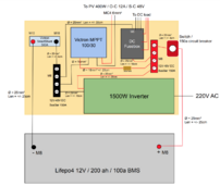
van-solar.png

Does this look ok ? Would you do anything differently ?
(This is my first ever build and I am not very sure of myself - I am kind of hoping if anyone has any advice now - before buying anything - in case my design needs changing...)

And my main question is regarding the cable sizes : Do they respect the (EU) norms for this size system? (ie 25mm² everywhere except to/from the MPPT which supports 16mm² max)
The cable sizes seem a bit overkill to me, given my usage (I guess 99% of the time used I will be drawing 3 to 4 amps for charging phone / laptop)
Still, the battery supports 100a max discharge, so I would like to keep the possibility to use the occasional 1000W appliance (blender or whatever).

Also, does this system require an earth ? and if so how would one go about earthing in a van? I know the vehicle electronics are/may be grounded to the chasis. If I also ground to the chasis couldn't that damage the inbuilt vehicle electronics in case of short-circuit ?

Any advice much appreciated 🙏🙏
 
Last edited:
The 150A bus bar and switch/breaker look too small:

1500W inverter / .85 efficiency / 10V cutoff = 176A
Thanks for your remark @MisterSandals !

Is the 10V cutoff value the same for all LiFePo4 12V batteries ? (does it correspond to the 0% SOC voltage ?)
If so, and supposing I wanted to prevent battery from draining under 20% (12.8V at 20% SOC) should I use a 137A breaker ? (1500 / 0.85 / 12.8)
And if I use that 150A breaker, then the circuit would cut off at 11.76V - ie somewhere between 0% and 10% SOC ?

Is my reasoning correct ? If so, I think I am happy with the 150A breaker to prolong battery life by preventing full discharge.

Also shouldn't the battery's built-in 100A BMS cut off first if I am trying to pull out 1500W when at 5-10% SOC ?
 
Last edited:
Is the 10V cutoff value the same for all LiFePo4 12V batteries ?
10V cutoff (probably) for your inverter.
If so, and supposing I wanted to prevent battery from draining under 20% (12.8V at 20% SOC) should I use a 137A breaker ?
No a breaker opens the circuit when amps are exceeded. They do not work based on volts.
You set your BMS to protect your battery from harm ( ~2.7V low, 3.63V high for my conservative settings).
Low voltage cutoff with an inverter is tricky as there aren't any easy solutions. Fortunately you can run your batteries in the full range (or just within) occasionally without harm.
Also shouldn't the battery's built-in 100A BMS cut off first if I am trying to pull out 1500W when at 5-10% SOC ?
Yes BMS cutoff at 100A. SoC cutoff usually based on voltage, not amps.
 
10V cutoff (probably) for your inverter.

No a breaker opens the circuit when amps are exceeded. They do not work based on volts.
You set your BMS to protect your battery from harm ( ~2.7V low, 3.63V high for my conservative settings).
Low voltage cutoff with an inverter is tricky as there aren't any easy solutions. Fortunately you can run your batteries in the full range (or just within) occasionally without harm.

Yes BMS cutoff at 100A. SoC cutoff usually based on voltage, not amps.
I see ! So I should swap them for 180A or 200A busbars and breaker
 
So I should swap them for 180A or 200A busbars and breaker
The key item is that you have a properly rated breaker/fuse to protect the wires and bus bars. If the breaker/fuse is too low amperage, you may get nuisance trips but that is protecting everything downstream from excessive current.

An LiFePO4 battery would ideally have a class T fuse at the battery because the current potential is tremendous. Some use MRBF fuses on the battery and i've not seen any problems from that (maybe someone else can point to a problem case?).

If you have a 100A BMS, then maybe 150A breaker/fuse and 180A/200A bus bar sufficient. But if you ever upgrade your battery or BMS 150A may be limiting and cause nuisance trips.

Sorry to ramble, please ask if this is not clear.
 
I am a big fan of MRBF fuse attached to the battery post. It will protect against an accidental short no matter what you do. People recommend blue sea systems, but they are typically just relabeling Eaton, Bussman, and Littlefuse and increasing the price. Make sure to use the MRBF mount block, the fuses don't connect directly to the bolt.

I am also a big fan on no-ox-id on all connections. It is a anti-corrosion conductive grease. It will cut through any oxides on the terminal now and prevent any more from forming. Takes just a dab.

I would do wires and bus bars and switches for 300 amps in case you ever want to upgrade your inverter. Fuses are to protect wires only. The breaker in this case is not needed and should just be a switch. The difference in price for these larger components is way smaller than replacing it all later.

I would make the MRBF on the battery post 25% over the BMS max out, so 125a. Any added batteries in parallel would be fused similarly.

If you ever want to upgrade you just add another battery or two in parallel and change the inverter. You can do 2000w with one battery added and 3000w with two batteries added. Benefit is the larger wires now have lower losses and less resistance. If you want to add an AC for instance.
 
Back
Top