diy solar

diy solar

EVE 105 48v 2p16s build

But how is SOC calculated just the charger? Or via a shunt?

I guess if the cells were at resting voltage of more like 3.35-3.4v then a load applied it’d be interesting to see what the sag was.
@740GLE SOC is taken from the JK BMS (non-inverter older one).

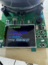
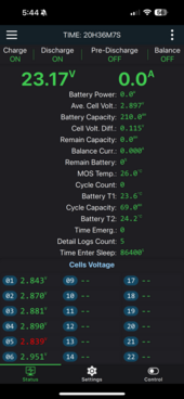
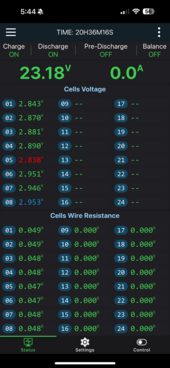
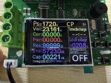
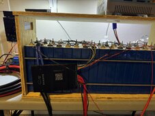
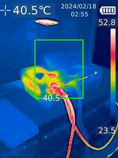
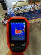
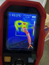
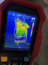
Here is a view after a charge to 3.45v per cell, followed by a few minutes by a 10a load then a 30a load applied. Interested to know what you're thinking.
1708113270015.png
 
I just finish testing the pack. Here the result.
 

Attachments

  • IMG_4872.jpeg
    IMG_4872.jpeg
    175.9 KB · Views: 11
  • IMG_4875.png
    IMG_4875.png
    228.3 KB · Views: 12
  • IMG_4876.png
    IMG_4876.png
    245.5 KB · Views: 11
  • IMG_4874.jpeg
    IMG_4874.jpeg
    323.7 KB · Views: 13
  • IMG_4877-compressed.jpeg
    IMG_4877-compressed.jpeg
    256.6 KB · Views: 12
I just finish testing the pack. Here the result.
Awesome, So you’re getting the expected AH out of these cells. Do you have a trend of cell voltages through the discharge cycle. Looking to see if your pack voltage sag aligns with my 48v pack.
 
Last edited:
Awesome, So you’re getting the expected AH out of these cells. Do you have a trend of cell voltages through the discharge cycle. Looking to see if your pack voltage sag aligns with my 48v pack.
How can I get that information?
 
Didn’t even think about temperature impact on cell discharge. My cells are in the basement of our cabin and it’s 10°C there at the moment as seen in the temp probes on the BMS and confirmed by my tempstick device (awesome product by the way). The discharge curve and voltage drop is different below 25°C as seen in the EVE 105ah data sheet below. They only have -20°C listed in the sheet but I assume sag gets progressively worse from 25°-> -20°. Think this answers my voltage sag concern/question. Thoughts? Last picture is a 87a load on the battery so about 4300w.
IMG_4629.png

IMG_4623.jpeg
1708182626832.png
 
Testing the new toy . Charging at 35A.
 

Attachments

  • IMG_0003-T.jpeg
    IMG_0003-T.jpeg
    25.3 KB · Views: 8
  • IMG_0003.jpg
    IMG_0003.jpg
    58.3 KB · Views: 8
  • IMG_0002-T.jpeg
    IMG_0002-T.jpeg
    23.5 KB · Views: 9
  • IMG_0002.jpg
    IMG_0002.jpg
    59.1 KB · Views: 9
  • IMG_0001-T.jpg
    IMG_0001-T.jpg
    21.7 KB · Views: 9
  • IMG_0001.jpg
    IMG_0001.jpg
    53.7 KB · Views: 8
More
 

Attachments

  • IMG_4884-compressed.jpeg
    IMG_4884-compressed.jpeg
    103.7 KB · Views: 12
  • IMG_4887-compressed.jpeg
    IMG_4887-compressed.jpeg
    111.9 KB · Views: 10
  • IMG_4886-compressed.jpeg
    IMG_4886-compressed.jpeg
    168.8 KB · Views: 9
  • IMG_4885-compressed.jpeg
    IMG_4885-compressed.jpeg
    131.7 KB · Views: 9
  • IMG_4888-compressed.jpeg
    IMG_4888-compressed.jpeg
    126.7 KB · Views: 9
  • IMG_4889-compressed.jpeg
    IMG_4889-compressed.jpeg
    129.2 KB · Views: 11
  • IMG_4890-compressed.jpeg
    IMG_4890-compressed.jpeg
    77.5 KB · Views: 12
That’s looks awesome. Seems to be $240 US on Aliexpress. Any problems with it yet?
I am still testing but is very well made. Looks like American good quality very beefy. It record everything and take pictures and time laps. Amazing for the price. Amazon has it for about $600

It took less than 2 weeks to arrive.
 
This one was the seller.

Just found this amazing item on AliExpress. Check it out! $231.00 50% Off | Uni-t Uti260A Uti260B Thermal Imager Camera 256x192 Image Thermographic Construction Repair Infrared Water Leak Electronics Home
 
So still screwing around with this pack. Learning more and more based on what I think the voltage sag cause is which changes daily. Now I’m into busbars again.

Check my math and here may be the problem:
Copper=1.2a/mm2.
Busbars: 12.5mm x 2mm = 25mm2
Busbar Amps: 25mm x 1.2a/mm2 = 30amp max.

Does this mean the max the busbars that came with the 105ah cells is 48v x 30a = 1440 watts?
I stacked my busbars with 2 for each.
 
Those are wider and little thicker than the ones that came with my batteries and look to handle 49amps. Two of those on every connection would get you to a .5c discharge of 100amps with 2p16s which is actually 200a.
@ZEUS-FL do you know what size bus bars you ordered for your 105ah cells. They have a few choices and I’m not at my batteries to measure. Looks like the 1.57in Pitch-Row is the right size. But want to make sure.
 
Last edited:
Back
Top