diy solar

diy solar

Explain Specifications on LifePO4 with inaccessible internal BMS

garetwo

New Member
Joined
Nov 4, 2023
Messages
183
Location
California Foothills
This should probably be in the BEGINNER section…but this forum looks very specific. I am an electrician learning about PV systems, I have a client trying to become as off-grid as he can. He has a system with a small PV array feeding into four inverters: SunGold Power 6.5KW BluePower SP6548 SOLAR INVERTER / CHARGER.

There are sixteen batteries. I am still trying to fully grasp 4S4P versus 4P4S and why there is a choice – I apologize for this and many areas where I lack understanding.

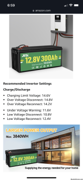
These sixteen JITA LifePO4 12.8Vdc 300Ah batteries have a spec sheet:

PER BATTERY
Nominal Voltage
12.8​
VDC
Charge protection voltage
14.2​
-14.6VDC
Discharge protection voltage
10.0​
-10.8VDC
Maximum continuous charging curent100AMPS
Maximum continuous discharging current200AMPS
Temp range CHARGE
32​
~122Fahernheit
Temp range DISCHARGE
-4​
~140Fahernheit

The inverters have settings for charging the battery bank. Do the specs above mean the non-accessible BMS provides a range of protection and we should set the charger rates to be in the middle?

Does discharge protection voltage mean it will drop out a cell somewhere from 10-10.8Vdc so we should try to maintain a charge above 10.8?
 
The SunGold Power 6.5KW BluePower SP6548 SOLAR INVERTER / CHARGER. is a 48V system that requires 48V batteries.
It is NOT wise to use 12V batteries in series to make a 48V power source. There are far too many issues with such - Just don't do it. This is a Bodge that will cause issues... There are far too may here who have learned this expensive lesson.

A 48V LFP battery pack consists of 16 LFP Cells, 1 BMS (Battery Management System), and a Breaker/Fuse.

Also be aware that at this time, you can get 48V/100AH Rackmountable battery packs in USA for $1300 from a Quality Manufacturer.
There are others as well, but Bang per buck with "all the goodies" these are a great option for getting it right the first time.
 
I agree with @Steve_S 4 12 volts in series will be a pain later.
it sounds like this is already purchased?
Yes. Twelve were initially purchased and online for, I am guessing, several months. Then four more were added along with two more inverters. I have been studying as much as possible, the learning curve has been a tad steep. I do see purchasing a 48-volt rack mount with BMS and communication as a system more easily monitored and maintained, but this is where we are at, so I am trying to help make it as good as can be. But, perhaps going rack mount before purchasing and installing equalizers, and messing with all these settings, may be better in the long run.

I would still like to understand the settings on the inverter relative to the specs for the batteries.
 
I would still like to understand the settings on the inverter relative to the specs for the batteries.
Should be the same as any other 48V LiFePO4 battery:
 
Yes. Twelve were initially purchased and online for, I am guessing, several months. Then four more were added along with two more inverters. I have been studying as much as possible, the learning curve has been a tad steep. I do see purchasing a 48-volt rack mount with BMS and communication as a system more easily monitored and maintained, but this is where we are at, so I am trying to help make it as good as can be. But, perhaps going rack mount before purchasing and installing equalizers, and messing with all these settings, may be better in the long run.

I would still like to understand the settings on the inverter relative to the specs for the batteries.
The problem you’re probably going to have is two fold. Balance between batteries as well as internal balance between cells within the batteries. The algorithm of the Voltronic 6548 family of inverters does not necessarily allow enough absorption time to allow proper cell balance for batteries that have passive balancing in open loop (no communication/networked batteries). The likelihood that the batteries will eventually trigger a high cell voltage charge disconnect is great and since the batteries have no display or Bluetooth, you may only realize a problem by diminishing performance.

Then there’s the 12 volt battery to battery imbalance that could happen regardless of the inverter type and yes, a balancer/equalizer could help that.

If it were me, I’d be cutting the tops off, removing the 12 volt bms’s and make 16S 300ah batteries with several JK bms’s. I wouldn’t go less than 2 amp balancing current for every 300 Ah because of the inverter’s short absorption/bulk profile.
I would then suggest the inverter settings of battery type “USE”, bulk “CV” 55.2 volts and float voltage “FLV” 54 volts.
A safer, easier way is to go with rack mount batteries that are networked however even they would need frequent excursions to 100% state of charge if they don’t have an active balancer to keep them in line. You could of course, add(surgery) an inexpensive Heltec balancer with a voltage start controller (to start balance at about 3.42 volts per cell) to each rack battery if they don’t have an active balancer to make them much less troublesome and reduce the stressful time held at bulk voltage needed for a passive balancer.
 
Should be the same as any other 48V LiFePO4 battery:
I see within the settings for the inverter (setting 05):
Flooded
User Defined
Pylontech
WECO
Soltaro
Lib-protocol compatible
3rd party Lithium

I only assumed from this that there is not a standard battery LifePO4 battery. I still cannot find a definitive answer on what "lib-protocol compatible" means. Most choices automatically set three or four other parameters within setup, 02(for most), then all the rest also 26, 27, and 29.

02: max charging amps, default 60A
26: Bulk charging voltage, default 56.4
27: Floating Charge voltage, default 54.0
29: Low DC cutoff voltage, default 44.0

These do not touch Battery Equalization parameters in 30, 31, 33, 34, 35, and 36.
I assumed (yes, I know what that spells) that all of these settings are a per battery value. So, if a battery specification (only as an example) has a maximum continuous charging current of 100, my brain was sort of exploding. How do I calculate what the max is that I can provide to all of these batteries in series and in parallel? How do I set things so that an internal BMS does not open? Then I thought...I will ask because I am very unsure.
 
Last edited:
Then there’s the 12 volt battery to battery imbalance that could happen regardless of the inverter type and yes, a balancer/equalizer could help that.

If it were me, I’d be cutting the tops off, removing the 12 volt bms’s and make 16S 300ah batteries with several JK bms’s. I wouldn’t go less than 2 amp balancing current for every 300 Ah because of the inverter’s short absorption/bulk profile.
I would then suggest the inverter settings of battery type “USE”, bulk “CV” 55.2 volts and float voltage “FLV” 54 volts.
This is appreciated, how to work with what there is in place. Cutting the tops off...that would be something if the owner/client would dare to go for it, it just seems that one would want an "expert" in this doing so.

I can also see how this adds to what Steve_S said" Also be aware that at this time, you can get 48V/100AH Rack mountable battery packs in USA for $1300 from a Quality Manufacturer". I wonder what the cost per amp-hour will be once all is said and done.
 
I see within the settings for the uinverter (setting 05):
Flooded
User Defined
Pylontech
WECO
Soltaro
Lib-protocol compatible
3rd party Lithium

I only assumed from this that there is not a standard battery LifePO4 battery. I still cannot find a definitive answer on what "lib-protocol compatible" means. Most choices automatically set three or four other parameters within setup, 02(for most), then all the rest also 26, 27, and 29.

02: max charging amps, default 60A
26: Bulk charging voltage, default 56.4
27: Floating Charge voltage, default 54.0
29: Low DC cutoff voltage, default 44.0

These do not touch Battery Equalization parameters in 30, 31, 33, 34, 35, and 36.
I assumed (yes, I know what that spells) that all of these settings are a per battery value. So, if a battery specification (only as an example) has a maximum continuous charging current of 100, my brain was sort of exploding. How do I calculate what the max is that I can provide to all of these batteries in series and in parallel? How do I set things so that an internal BMS does not open? The I thought...I will ask because I am very unsure.
All of your assumptions are mostly correct and not troubling. Under user defined there are safe defaults that are good to start with. You would basically take the factory recommendations for a 12 volt battery and times 4 for a 48 volt system. Be aware that any one battery in series can trigger a release so you may want to give a buffer to the upper and lower recommendations. The dilemma is getting it close to the higher voltage so the battery’s internal balancer can work without one of them triggering a high high cell voltage too often, preferably next to never. Be aware that the inverters are not to be run battery less when setup for split phase. If the batteries go into low voltage safety, they will not restart until their hits reconnect voltage, so unless you have a big 48 volt charger around I’d set the inverter’s low voltage disconnect and shutdown well before the batteries. The current is max 60 amps for each group of 4 batteries you put into series. So if you have four batteries in series and you have a total of four like that in parallel, you could theoretically charge 240 amps. However I’m assuming that you will have each bank of four going to a buss bar and not cross tied parallel. This is the better way because you can better fuses and switch out each bank as needed. I wouldn’t utilize the full charge current because when wired this way one bank can take more charge than another so I’d back off the total charge current to something less likely to trigger a high voltage in one of the rows, say 150 amps to start with. You could verify how things are going with a good DC clamp meter. Since this is a unique system, you know the individual battery parameters and you will have to spend time with to watch and see what it’s doing. Not ideal and let the consumer know that you are limited by what the customer purchased. I’d spend some time educating the customer so you don’t end up living there.
I’d be using 2/0 to each battery and jumpers up to a buss for each row of batteries. Each inverter would be connected to the buss with 2/0 cables and each inverter should have its own current interrupt. No cheap no name breakers. Remember to pre-charge each inverter just before you close the circuit. Or you could damage the inverter or batteries from the inrush current.


IMG_1110.png
 
Last edited:
This is appreciated, how to work with what there is in place. Cutting the tops off...that would be something if the owner/client would dare to go for it, it just seems that one would want an "expert" in this doing so.

I can also see how this adds to what Steve_S said" Also be aware that at this time, you can get 48V/100AH Rack mountable battery packs in USA for $1300 from a Quality Manufacturer". I wonder what the cost per amp-hour will be once all is said and done.
Yeah, I should have put a bigger emphasis on “what I would do” LOL. It is indeed expert territory or above the norm install. Probably what I’m trying to relate is that you are basically blind to what’s going on in each battery and it’s going to take some monitoring manually and some tweaking to find what works.
 
4P4S vs 4S4P usually refers to parallel cross strapping 12v batteries before series connecting four groups of the four parallel batteries in series.

You have to assume any single battery's BMS may shut down for some reason.

It is better to have a single series string of four batteries taken out by one of the series connected battery's bms. This keeps the current consistently matching through the four series connected batteries. Connect array as four independent, four series string, batteries. It also allows you to remove one series string for servicing while leaving the other three strings connected to run the system.

It is advisable to have individual battery monitors on each independent series string and keep tabs on total current sharing across each of the independent series strings. Don't expect current sharing variance to be much better than 15-20%. Cable resistance matching is important to current sharing.

You must be sure the 12v batteries' internal BMS is capable of handling the total series stack voltage. Battery specs should state they can be series stacked up to four batteries.
 
All of your assumptions are mostly correct and not troubling. Under user defined there are safe defaults that are good to start with. You would basically take the factory recommendations for a 12 volt battery and times 4 for a 48 volt system. Be aware that any one battery in series can trigger a release so you may want to give a buffer to the upper and lower recommendations. The dilemma is getting it close to the higher voltage so the battery’s internal balancer can work without one of them triggering a high high cell voltage too often, preferably next to never. Be aware that the inverters are not to be run battery less when setup for split phase. If the batteries go into low voltage safety, they will not restart until their hits reconnect voltage, so unless you have a big 48 volt charger around I’d set the inverter’s low voltage disconnect and shutdown well before the batteries. The current is max 60 amps for each group of 4 batteries you put into series. So if you have four batteries in series and you have a total of four like that in parallel, you could theoretically charge 240 amps. However I’m assuming that you will have each bank of four going to a buss bar and not cross tied parallel. This is the better way because you can better fuses and switch out each bank as needed. I wouldn’t utilize the full charge current because when wired this way one bank can take more charge than another so I’d back off the total charge current to something less likely to trigger a high voltage in one of the rows, say 150 amps to start with. You could verify how things are going with a good DC clamp meter. Since this is a unique system, you know the individual battery parameters and you will have to spend time with to watch and see what it’s doing. Not ideal and let the consumer know that you are limited by what the customer purchased. I’d spend some time educating the customer so you don’t end up living there.
I’d be using 2/0 to each battery and jumpers up to a buss for each row of batteries. Each inverter would be connected to the buss with 2/0 cables and each inverter should have its own current interrupt. No cheap no name breakers. Remember to pre-charge each inverter just before you close the circuit. Or you could damage the inverter or batteries from the inrush current.


View attachment 177374
GREAT info, thank you. I realize all of this now is just to do the best possible with what is in place, not establish what would have been a better installation. However, I have saved all of that information as well!
 
4P4S vs 4S4P usually refers to parallel cross strapping 12v batteries before series connecting four groups of the four parallel batteries in series.

You have to assume any single battery's BMS may shut down for some reason.

It is better to have a single series string of four batteries taken out by one of the series connected battery's bms. This keeps the current consistently matching through the four series connected batteries. Connect array as four independent, four series string, batteries. It also allows you to remove one series string for servicing while leaving the other three strings connected to run the system.

It is advisable to have individual battery monitors on each independent series string and keep tabs on total current sharing across each of the independent series strings. Don't expect current sharing variance to be much better than 15-20%. Cable resistance matching is important to current sharing.

You must be sure the 12v batteries' internal BMS is capable of handling the total series stack voltage. Battery specs should state they can be series stacked up to four batteries.
Well said
 
4P4S vs 4S4P usually refers to parallel cross strapping 12v batteries before series connecting four groups of the four parallel batteries in series.

You have to assume any single battery's BMS may shut down for some reason.

It is better to have a single series string of four batteries taken out by one of the series connected battery's bms. This keeps the current consistently matching through the four series connected batteries. Connect array as four independent, four series string, batteries. It also allows you to remove one series string for servicing while leaving the other three strings connected to run the system.

It is advisable to have individual battery monitors on each independent series string and keep tabs on total current sharing across each of the independent series strings. Don't expect current sharing variance to be much better than 15-20%. Cable resistance matching is important to current sharing.

You must be sure the 12v batteries' internal BMS is capable of handling the total series stack voltage. Battery specs should state they can be series stacked up to four batteries.
Thank you. So there are things that may be added to help strengthen reliability. A new input here is the independent monitoring of each string of four in series. They are all tied to a common bus, how do you segregate the monitoring? What is being monitored? And, how do make use of the data - opening/closing of contacts, alarm, notification via an app?
 
Thank you. So there are things that may be added to help strengthen reliability. A new input here is the independent monitoring of each string of four in series. They are all tied to a common bus, how do you segregate the monitoring? What is being monitored? And, how do make use of the data - opening/closing of contacts, alarm, notification via an app?
Four independent current shunts, one on each string.
 
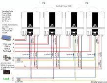
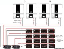
Just so they are posted, I thought I had View attachment 177385View attachment 177386

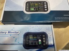
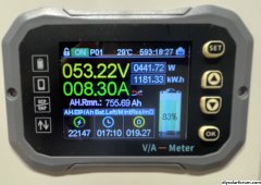
I see no problems with this diagram. Like RC said you could use a shunt between each row of batteries and a fifth to measure the overall. It’s just going to add to the complexity and cost, much of which could have been avoided with a different battery but that spilled milk at this point. Of the shunts out there, the quality and the current range dictates the price. There are many that are clones of each other sold under different names but identical in performance that look like ones the picture. The older version has the display has the cell in the vertical position and the newer is horizontal. The newer version has an enclosure around the shunt. I’ve tested both and both are amazingly accurate and the apps which I believe can be addressed so you can look at each individually work well. IMHO it’s these (nothing less) or the Cadillac of the shunts the Victron. Victron has an app but if you want a display, it must be purchased separately $$$.
IMG_0960.jpegIMG_0964.jpeg
 
Last edited:
The units pictured do have parameter configured dry contact options for voltage and current.
 
Another option is to purchase the Solar Assistant for monitoring all four inverters anywhere in the world with many remote controls. It works better than the network built in to the the inverters. Solar Assistant will monitor only one Victon shunt (overall battery capacity) and no connection at all to the types pictured as far as I know. So you could use the four cheaper shunts for local individual row status only. It will see many other types of rack batteries and bms brands just for future reference. You can see it’s only a matter of time, money and a learning curve ?
 
Back
Top