diy solar

diy solar

Feasible to wire inverter AC out myself into a breaker box?

AlaskanNoob

Solar Enthusiast
Joined
Feb 20, 2021
Messages
946
I have no electrical skills and I'm not particularly bright, but I did manage to get the bus bar set up the MPPT, PV, Quattro and the batteries without blowing anything up. And I trenched the solar shed to the cabin 600 feet away and the fiber optic works so I assume the huge power cable will also. Having trouble getting an electrician up to our off grid homestead, so considering doing these two things myself:

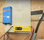
1. SOLAR SHED: wiring the Victron Quattro AC1 Out (somehow) to our aluminum 250-250-4/0 cable that goes to the cabin. Note: that AT in the solar shed picture is for later when we wire up the solar shed as well, but for now I'd just like to get electricity to the cabin. There will be another AT at the cabin.
SS.jpg

2. CABIN: wiring that same aluminum cable into a Victron AutoTransformer (I have it, just haven't put it up on the wall yet) and then into a breaker box with two temp 120V outlets (so I can balance the loads on the AT)
Mud.jpg

But I think the aluminum cable presents challenges beyond having a non-electrician dummy working with AC power. But since we're struggling to find an electrician and we got snow on the ground for the first time today, I'm considering it. Which is probably a bad idea. But I'm sitting on 38KW of battery power in the solar shed all ready and waiting to be used, and a fat wire connecting to the cabin, but unless I can get somebody up here to complete the task, it's just sitting there unused. And as it gets colder and snowier, the prospect of getting somebody up seems lesser. One electrician we had scheduled a long time out had a family emergency and we're having a tough time finding a replacement that wants to come up.

EDIT: never mind, it's a bad idea. We'll keep trying to get an electrician up.
 
Last edited:
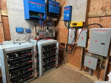
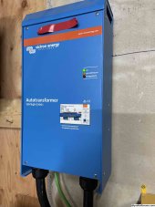
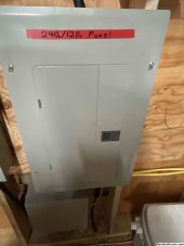
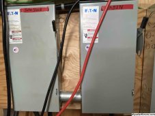
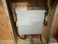
Turns out, it wasn't that hard. We now have 240/120V power in our solar shed AND 240/120V power in the cabin 600 feet away. A is the cut-off switch for the solar shed 240/120V power. B is the cut-off switch for the cabin's 240/120V power. C is the breaker box for the solar shed power. D is the J Box where B connects to our huge 250/250/4-odd cable that goes 600 feet to the cabin. And E is the AutoTransformer for the solar shed. Not shown is a 50 amp outlet outside our solar shed for running a welder and a couple 120V outlets in the solar shed.

At the cabin (not shown) we have another J box to receive the power which feeds into a second AutoTransformer which goes into another breaker box, a 240V outlet for a heat pump that we're getting installed, and some 120V outlets in the cabin.

So how did a noob like myself do it? Simple. I set up the Quattro to output 240V and 60hz power and I disabled the ground relay in it through the software. Then I got an electrician to come up. Simple!

Man it feels good to finally tap those batteries and not have to run a generator...


setup.jpg
 
Congratulations, it is so satisfying to produce and use your own power. I'm glad you found a sparky that would come out and help you.
 
I suppose I don't understand the whole setup. How is the cabin feeder grounded if only two wires are used?

I don't understand the setup either. Got a welder coming up today to use the 50A outlet to put 4 discs on our mounts and then we can finally mount our 7KW of panels. Then I'll start trying to figure out what the electrician did and to make sure it's all good (beyond the fact that it's supplying power to the shed and the cabin). I have a few questions though, especially about grounding.

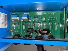
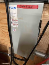
Quattro ground relay disabled. Four wires from Quattro go to a shutoff switch for the solar shed which is also plumbed to a shut off switch for the cabin. My understanding is one set goes to the solar shed cutoff switch and the other set passes through that solar shed cutoff switch to the cabin shutoff switch, so they are separate systems. You can see the two sets are doubled up on the inverter.

1.jpg


2.jpg

From the solar shed shutoff switch, cables go to solar shed Autotransformer.

3.jpg

Then from there it goes to the solar shed breaker panel. The breaker panel has a ground wire to the solar shed J box.

4.jpg

The cabin shutoff switch is plumbed to the J box. The J Box is where the power connects to two of the three triplex wires that are trenched to the cabin. The J box also has a bare copper ground to a ground rod by the solar shed.

5.jpg

6.jpg

600 feet away at the cabin, the two of the three triplex wires go into a cabin J box that also has a ground connected to the metal posts our deck and cabin sit on, and then goes to a cabin autotransformer and the autotransformer goes to the cabin breaker panel.

Everything else is not grounded. Batteries, MPPT, EG4 chargeverter are all floating from what I understand. There is a ground rod at the solar shed, and the cabin is grounded through a metal post.
 
OK, so 240 volts goes to the auto transformer making 120/240 for the shed and 240 volts goes to the cabin where another transformer makes 120/240 for the cabin. But just having an earth ground isn't sufficient. But this is a strange setup for the average electrician so I can understand how these things happen.

I THINK what should happen is, since the same 240 volt output feeds both buildings, that the neutral of the transformer in the shed should be bonded to ground and the unused 4/0 connected to it. Then at the cabin, that 4/0 is the EGC and kept separate from the cabin neutral.
 
What the fuck did that guy do, no ground, no neutral, doubling up wires, you cannot remark a ground wire as a current carrying conductor.
I just don't understand how people can get it so wrong.

Yeah, I'm sure we'll have to figure some things out about this. For one, the way they did it, I think precludes us expanding to supply power to a third location. The whole point of our architecture was to have this shed be the one distribution point for the entire property. So we could get another inverter and have more power supplied as our needs grow.

Given that he has double stacked the Quattro AC1 out terminals to supply power, I'm not sure we can do that. What I was envisioning was power going from AC Out of the Quattro to some kind of distribution box where it could then be split to several locations and expanded later.

But anyway, I don't have the brain bytes to try to understand let alone figure this out right now and winter is coming so I've got to do other things.

EDIT: but I hope the big brains here tear this apart so I can understand what needs fixed when we get some time.
 
Last edited:
What the fuck did that guy do, no ground, no neutral, doubling up wires, you cannot remark a ground wire as a current carrying conductor.
I just don't understand how people can get it so wrong.

Electrician coming back out on Monday to do a couple more small things. I will try to get a video of him explaining exactly what he did and why.
 
Can you elaborate? I'll try pass something useful to the electrician on Monday.
Go look at post #10. The neutral of the first transformer should be grounded and an EGC created there. The 4/0 is the ground to the cabin. At the cabin, another ground rod should be connected to it. The second transformer neutral won't be grounded again
 
Just have him read the manuals for the equipment you are having him install, if he doesn't understand it replace him.

Yeah, we made a detailed video and provided links to the manuals for all the equipment in advance and stressed the importance of understanding the Quattro and the Autotransformers. Sent the discussions we had with PYKS on it.

Then when he showed up we had to explain that the AC1 out and AC2 out of the Quattro did not both supply 240V out so he couldn't just wire one Autotransformer to each as he had planned. It was obvious he didn't do any real research. But getting people to watch our videos and do any research is too much to ask these days it seems. And we have a limited pool to work with around these parts.
 
Back
Top