OffGridForGood
Catch, make or grow everything you can.
Back to the same SOC they were when you installed them?I'm trying to find out how far to discharge to avoid any swelling.
Back to the same SOC they were when you installed them?I'm trying to find out how far to discharge to avoid any swelling.
I think 50-60% shoiuld work for new cells. My cells were two to three years old and as I mentioned, only three of them were swollen and they were all part of the same three cells in parallel. The other 45 were fine.I'm trying to find out how far to discharge to avoid any swelling. Of course the chance of it happening now that the cells are new is a lot less than after 2 years of cycling for example.
I think 50-60% shoiuld work for new cells. My cells were two to three years old and as I mentioned, only three of them were swollen and they were all part of the same three cells in parallel. The other 45 were fine.
Never had an issue, just used a precharge resistor before I turned back on.So, I'd like to ask, is there anyone here that had a charger/AIO damaged by a battery disconnect event?
Never had an issue, just used a precharge resistor before I turned back on.
Two questions, Is this precharge resistor something that can be used temporarily, while commissioning or does it typically stay in the circuit? I'm picturing pre connecting with alligator clips and removing it once tph battery connection is made.Never had an issue, just used a precharge resistor before I turned back on.
It is used just when making an initial connection.Two questions, Is this precharge resistor something that can be used temporarily, while commissioning or does it typically stay in the circuit? I'm picturing pre connecting with alligator clips and removing it once tph battery connection is made.
Second, Can you post a link to where I may purchase one?
TIA
Photo? I'd like to make on but I/m having difficulty picturing what it looks like.2P momentary switch and resistor set parallel to the main Pos Neg connection to inverter supply bus.
I bought the 2-pole momentary switch online, - just a rocker switch with a spring inside so it is only "on" while I am pushing on the button.Photo? I'd like to make on but I/m having difficulty picturing what it looks like.

Thank you for this. Way more elaborate than I pictured. I thought it was something like a jumper with alligator clips on each end.I bought the 2-pole momentary switch online, - just a rocker switch with a spring inside so it is only "on" while I am pushing on the button.
Wire the pos and neg from main bus to the inverter input DC buses around your main disconnect for the ESS, and put a resistor on the Pos lead.
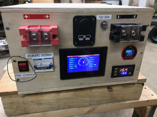
Here is a pic of a similar set up on my mobile DIY 8s pack. The main 2P Pack breaker in the photo is "ON". To precharge this breaker will be "OFF", then press and hold the precharge to charge up the inverter capacitors, then switch the breaker to "ON" with your other hand, and then let go of the pre-charge switch.
Electrically, the Line side neg is wired to the Main battery Neg, and the Load side Neg is wired to the pack terminal Neg. the Line side Pos is wired to the BMS output Pos, and the Load side Pos is connected to a small resistor (ebay/amazon/aliexpress) then to the pack terminal Pos.
{ As an added bit of protection I put an online automotive 10A fuse wired between the resistor and the pack terminal Pos - just to protect the small wire since otherwise the only protection is the BMS which on this pack is 150A which is too high for the small pre-charge wire ga.}
View attachment 209123
That's what I'm trying to make. I have been building DIY lithium batteries for friends and, while I haven't had a problem yet, would like to avoid the initial CRACK when first connecting the inverter. Once up and running, it won't be needed.I "try" to keep alligator clips for temporary stuff/testing.
Here's the resistor I use. YiePhiot 2PCS 50W 25 Ohm Resistor Aluminum Case Wirewound Chassis Mounted Compatible with Ring Doorbell, Nest Hello Doorbell, SkyBell Doorbell Etc https://a.co/d/7QaQHu6Two questions, Is this precharge resistor something that can be used temporarily, while commissioning or does it typically stay in the circuit? I'm picturing pre connecting with alligator clips and removing it once tph battery connection is made.
Second, Can you post a link to where I may purchase one?
TIA
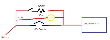
I built mine with a small project box, a momentary contact button, a LED, and a resistor to go around the main breaker. Since my systems are only used occasionally I tend to shut everything down so the pre charge resistor is Step 1 in my startup instructions. I have a small wire connected to each leg of the main DC breaker so the power goes in from the battery, around the main breaker, and out to the inverter.Two questions, Is this precharge resistor something that can be used temporarily, while commissioning or does it typically stay in the circuit? I'm picturing pre connecting with alligator clips and removing it once tph battery connection is made.
Second, Can you post a link to where I may purchase one?
TIA

Exactly what I'm thinking of. Thanks.I built mine with a small project box, a momentary contact button, a LED, and a resistor to go around the main breaker. Since my systems are only used occasionally I tend to shut everything down so the pre charge resistor is Step 1 in my startup instructions. I have a small wire connected to each leg of the main DC breaker so the power goes in from the battery, around the main breaker, and out to the inverter.
Here's a wiring diagram of what I build with example numbers:
View attachment 209143


