diy solar

diy solar

First 3kw DIY solar with PowMr split phase inverter10kw

Rconce01

New Member
Joined
Mar 26, 2024
Messages
35
Location
Florida
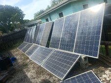
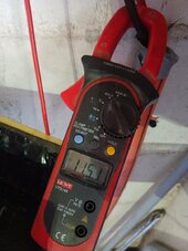
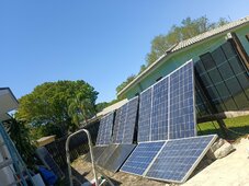
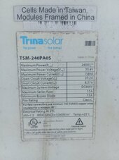
New here looking for some guidance and feedback. I built a small array of panels looking to get approx 3kw of power. I connected everything in series after testing each panel and I got approx 480v at 6.2 amps (short circuit with amp meter)

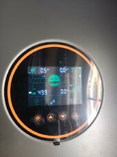
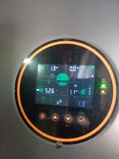
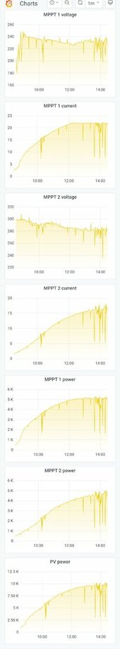
I thought I would expand the system and i got the large Powmr 10k split phase and despite using 8 gauge wiring and confirming the power is getting to the inverter it only reads about .5kw on the PV input. Is this thing trash or did I do something wrong?

I figured I should be getting at least 2kw out of a 3kw system right?
 

Attachments

  • IMG_20240326_124534_872.jpg
    IMG_20240326_124534_872.jpg
    114.9 KB · Views: 35
  • IMG_20240326_155604_609.jpg
    IMG_20240326_155604_609.jpg
    466.5 KB · Views: 35
480Voc is VERY high unless you have a 600Voc MPPT. The MPPT voltage is a NEVER EXCEED value.

All panels in the same string must face the same direction. All panels will perform no better than the worst orientation panel.

Shading may also challenge the MPPT's ability to find the max power point.
The max pv input voltage is 500v on the inverter. I figured the higher the better. Should I string them up as 7s 2p? I figured 14s is more effective use of the power.
 
The max pv input voltage is 500v on the inverter. I figured the higher the better. Should I string them up as 7s 2p? I figured 14s is more effective use of the power.
Agree with @sunshine_eggo .
Restring ASAP you're flirting with a magic smoke party.

500V is the max but what's the working range in the manual...
 
If he gets 480voc the string would likely be around 390v while it's working. He may be just fine
It may be fine to run that high but it's not worth the gamble in my opinion.
A cold day and batteries hit float...

It's also outside the working voltage range so...
Screenshot from the SRNE ASF manual but it's the same AIO
Screenshot_20240326-214132.jpg

I count 15 panels, I'd rewire 5s3p into a combiner box and make sure each string is on the same plane.

Securing the panels is a whole separate topic that should be addressed.

Oh welcome to the forum @Rconce01 you'll be happy with the inverter and get great support here.
 

Attachments

  • Screenshot_20240326-213807.jpg
    Screenshot_20240326-213807.jpg
    38.6 KB · Views: 8
It may be fine to run that high but it's not worth the gamble in my opinion.
A cold day and batteries hit float...

It's also outside the working voltage range so...
Screenshot from the SRNE ASF manual but it's the same AIO
View attachment 204994

I count 15 panels, I'd rewire 5s3p into a combiner box and make sure each string is on the same plane.

Securing the panels is a whole separate topic that should be addressed.

Oh welcome to the forum @Rconce01 you'll be happy with the inverter and get great support here.
Awesome thank you all for the feedback. Yes I understand the panels would need to be secured. As far as the recommended working voltage I didn't see anything in the manual and the inverter has over voltage PV protection. But I can certainly do a 5s 3p. Ideally I just want to see the PV input reading at least 2kw not .5kw with all those panels.
I measured them all and they are around 33v 5-6amp each.


Typically what's the net loss in power between the watts calculated based on short circuit current and the PV input reading on the Inverter?
 
Awesome thank you all for the feedback. Yes I understand the panels would need to be secured. As far as the recommended working voltage I didn't see anything in the manual and the inverter has over voltage PV protection. But I can certainly do a 5s 3p. Ideally I just want to see the PV input reading at least 2kw not .5kw with all those panels.
I measured them all and they are around 33v 5-6amp each.
You're welcome.
Might be better off going 7s2p to get the voltage higher, 5s will be just above the bottom.
Typically what's the net loss in power between the watts calculated based on short circuit current and the PV input reading on the Inverter?
Depends on lots of variables... I see calculated or higher in ideal conditions and angle.
 
I got the 5s 3p setup and it works out much better than everything in series. Voltage is 166v and I measured short circuit amperage and it's 30 amps.

Hooked up to the inverter under full load the PV panel circuit ramps up to about 13 amps then voltage drop becomes under 100v and the inverter resets.

I'm still puzzled how an array of 15 panels averaging about 180w which is about 2700w registers only 1300w on the inverter PV input.
 

Attachments

  • IMG_20240329_134218_573.jpg
    IMG_20240329_134218_573.jpg
    106.8 KB · Views: 11
  • IMG_20240329_134228_474.jpg
    IMG_20240329_134228_474.jpg
    106.1 KB · Views: 10
  • IMG_20240329_134646_477.jpg
    IMG_20240329_134646_477.jpg
    399.7 KB · Views: 10
I got the 5s 3p setup and it works out much better than everything in series. Voltage is 166v and I measured short circuit amperage and it's 30 amps.

Hooked up to the inverter under full load the PV panel circuit ramps up to about 13 amps then voltage drop becomes under 100v and the inverter resets.

I'm still puzzled how an array of 15 panels averaging about 180w which is about 2700w registers only 1300w on the inverter PV input.
It's the angle of the panels in relation to the sun.

In the attached screenshot from today you can see how angle has an impact.
MPPT 1 is the ground mount angled appropriately with 5180 watts of panels.
MPPT2 is roof mounts with 5670 watts of panels...
 

Attachments

  • Screenshot_20240329-142924.jpg
    Screenshot_20240329-142924.jpg
    28.4 KB · Views: 9
I got the 5s 3p setup and it works out much better than everything in series. Voltage is 166v and I measured short circuit amperage and it's 30 amps.

Hooked up to the inverter under full load the PV panel circuit ramps up to about 13 amps then voltage drop becomes under 100v and the inverter resets.

I'm still puzzled how an array of 15 panels averaging about 180w which is about 2700w registers only 1300w on the inverter PV input.
It looks like you have 2 different types of panels, this could also have an impact.

Wait a second, I'm an idiot, your inverter has 2 MPPT inputs, correct?

Are you using both of them currently or do have panels wired to only one.
 
Last edited:
It's the angle of the panels in relation to the sun.

In the attached screenshot from today you can see how angle has an impact.
MPPT 1 is the ground mount angled appropriately with 5180 watts of panels.
MPPT2 is roof mounts with 5670 watts of panels...
Awesome thanks for sharing so looking at mppt1 at noon is making approx 5000w of power which is 96% of the 5180. And mppt 2 is making 4000w which is 70% out of 5670.

How did you figure out the best angle for the ground mounted ones?
 
It looks like you have 2 different types of panels, this could also have an impact.

Wait a second, I'm an idiot, your inverter has 2 MPPT inputs, correct?

Are you using both of them currently or do have panels wired to only one.
I'm only using 1 input out of the two and yes those black panels are Longi and they produce same voltage but more current..I had 4 of them so I added them in to the first two 5s series.
 
Awesome thanks for sharing so looking at mppt1 at noon is making approx 5000w of power which is 96% of the 5180. And mppt 2 is making 4000w which is 70% out of 5670.
Yes and the roofs are not nearly as steep and the ground mount.
How did you figure out the best angle for the ground mounted ones?
I ran calculations through pvwatts and JRC. I also used this site http://www.solarelectricityhandbook.com/solar-angle-calculator.html but it seems to be down.

I'm only using 1 input out of the two and yes those black panels are Longi and they produce same voltage but more current..I had 4 of them so I added them in to the first two 5s series.
So the current will be limited by the lowest panels in the series string...
I would definitely make use of the 2nd mppt.
You have 11 of one panel and 4 of the Longi?
You might get away with 11S on 1 mppt and 4s on the other.

Could you share a photo of the labels for each type of panel?
 
It looks like you have 2 different types of panels, this could also have an impact.

Wait a second, I'm an idiot, your inverter has 2 MPPT inputs, correct?

Are you using both of them currently or do have panels wired to only one.
I have 18 Trina and 4 Longi.

They are all cracked panels but I verified all the diodes and they are putting out rated voltage but a about 20% less amps than the rated amount.

The Trinas are about 4-5 amps short circuit current each the the Longi are 8.5 amps each.
 

Attachments

  • IMG_20240329_185519_235.jpg
    IMG_20240329_185519_235.jpg
    114 KB · Views: 6
  • IMG_20240329_185547_202.jpg
    IMG_20240329_185547_202.jpg
    210.1 KB · Views: 6
I have 18 Trina and 4 Longi.

They are all cracked panels but I verified all the diodes and they are putting out rated voltage but a about 20% less amps than the rated amount.

The Trinas are about 4-5 amps short circuit current each the the Longi are 8.5 amps each.
I would not use the Trinas and Longi together in the same string. The Longi will work 4s to a separate MPPT but you might have poor performance in low light.
You could run your current 5s2p string of Trinas 10s without issue.
 
I have 18 Trina and 4 Longi.

They are all cracked panels but I verified all the diodes and they are putting out rated voltage but a about 20% less amps than the rated amount.

The Trinas are about 4-5 amps short circuit current each the the Longi are 8.5 amps each.
Imo, I would do 9s2p Trina into MPPT 1, maybe do 9 leaning against that wall/fence and the 9 below if that’s your location for them and then the 4 longi as its own string to MPPT 2
 
Back
Top