diy solar

diy solar

Grounding confusion - 3300W pure sine inverter on Wooden frame in laundry

I'm reading this with much interest. I have just finished building my first battery and connected it to the inverter and SCC for testing purposes. The plan was to connect an electric vehicle charger to the battery to charge the vehicle from the battery. Well, that failed because the EV charger says "Ground fault. Check wiring". The new battery system is totally off grid though and has no connection to any existing installation in my workshop.

The inverter is a Xijia 3000W and has two terminals for AC and a ground stud next to it. I grounded the stud to a sub board which is grounded to a earth rod just outside. This is all new cabling and working for other circuits. So ground, better call it earth, is all good.

I also opened the inverter and found the earth stud only connects to the earth pin of the socket. Nothing else.

To make the system work I need to create a new, separate TN-S system as we use here in Australia. This is for the inverter AC side to run RCDs
View attachment 35581

So I got in contact with Xijia and asked for advice. Well, they said the AC contacts are floating and have no connection to any earth or grounding and also cannot be grounded (no reason provided). If I measure, I have AC60V and AC48V between the AC contact and earth. But I guess this is just a floating potential and not really a voltage difference where current flows.

Seems like these inverters work but cannot be used for any sensitive loads or devices which actually check for safety, like the EV charger or medical equipment. And the manufacturer said I cannot create a new MEN link at the AC output... Has anyone tried?

So, is a new inverter the only option here? I much appreciate your feedback on this...


In many countries the TN-C(-S) system is used.
You got 2 cable: 1 Line (or 3 if 3 phase) and a PEN (-C ommon : neutral+earth) from utility (it is the TN-C).
You have to separate the PEN into Neutral and Earth in your box (that is the -S eparate part).
There is a bonding in your box between N and E.

If you have a TN-S system then you have 3 cables (or 5 if 3 phase) coming from grid: Line(1-2-3), Neutral and Earth.
In a TN-S system you do not have a connection/bond between the Earth and the Neutral.
Both coming from utility already separated and you are not allowed to short them.
You can (and should) add your own local earth to the Neutral cable tough. But not to the utility Earth.
It is called MEN - multiple earthed neutral.

Use breaker or better an RCBO in the AC output ! It can save your life. Also if a short occurs AC side it can save your inverter.


Also you have an off-grid system.
In this case you have to make the bond (TN-C as you did with that extra cable) and after that the TN-C-S separation (and then use an RCBO).

In many off-grid inverters there is a relay to do it.
If used with grid relay is OFF.
If grid goes down or offgrid system relay is on bonding Neutral to Earth.

Also Victron inverters are good, but very overpriced. You can buy 3-4 MPP Solar 5kW inverter from the price of 1 Victron 5kW inverter.

And you will need a 5kW inverter if you want continous 2-2.5 kW from it.
Most of the cases they say it is 3kW. It can even produce it for a longer time ... but it breaks if you (mis)use it all the time at near max output.

And you can parallel this 5kW inverters. For the price of 1 Victron 5kW you can get 3 MPP Solar 5kW paralleled in one phase 15 kW.
Or a 3 phase 5kW.
 
Last edited:
In a TN-S system you do not have a connection/bond between the Earth and the Neutral.
I would word that slightly differently:

" In a TN-S system you do not have a connection/bond between the Earth and the Neutral at the customer premise. "

There will be a bond at the utility transformer. That is what creates the low impedance path for clearing any shorts/faults to the non-conducting metal (Here in the states these are called ground faults.... but I do not like that name because it is not related to earth ground).

You can (and should) add your own local earth to the Neutral cable tough. But not to the utility Earth.
It is called MEN - multiple earthed neutral.
I don't know what the rules are in other countries, but I would advise to only do this at the service entrance if the rules allow it.

Doing it in multiple places is begging for problems in a lightning strike.
 
I would word that slightly differently:

" In a TN-S system you do not have a connection/bond between the Earth and the Neutral at the customer premise. "

There will be a bond at the utility transformer. That is what creates the low impedance path for clearing any shorts/faults to the non-conducting metal (Here in the states these are called ground faults.... but I do not like that name because it is not related to earth ground).

Yes in a TN-S system the bond is ONLY in the transformer ... so as I said "you do not have a connection/bond between the Earth and the Neutral." ;)


I don't know what the rules are in other countries, but I would advise to only do this at the service entrance if the rules allow it.

Doing it in multiple places is begging for problems in a lightning strike.

You can have more earthing rod connected to the same Earth cable. And you SHOULD if it is put into dry sand or rocky ground (check resistance).
Here is the rule if these rods are less than 20m away then you HAVE TO connect them directly to each other.

So if you have a shed 25m away then the rod you put down there does not need to be directly connected to the main rod.
 
Here is the rule if these rods are less than 20m away then you HAVE TO connect them directly to each other.
That is a good thing!!

So if you have a shed 25m away then the rod you put down there does not need to be directly connected to the main rod.

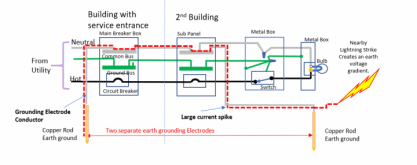
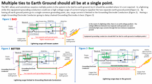
There are similar rules in the states for the grounding wires (not neutral)...... and it can cause problems in the event of a lightning storm.

The following describes the problem with multiple ground rods on the Equipment Grounding Conductor.

1612654314399.png

The good news is that as far as I can tell, you are never required to do something like shown in figure 1 but sadly, it is allowed.

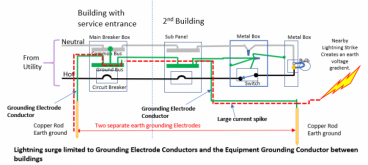
In the case of the separate building, there is an NEC a requirement to do something like this:
Edit: Added missing diagram
1612661033164.png

If you have multiple grounding points on neutral (MEN) you can have a similar situation:
1612653802137.png
These current spikes on the ground and/or neutral can and do play havoc on equipment.

So the logical question is "Why do they have us do another ground rod for the second building if it can create this large current spike?"
The answer is that you can also have a high energy, high frequency spike imposed on the wiring due to electro-magnetic pulse from the lightning (or other sources). If there is a long wire to the ground rod the natural impedance would block the high frequency spike from 'draining'. So.... which scenario is the worse? The voltage gradient across the earth causing a spike or the EMP from the lightning causing the spike? Clearly, the rules bodies think the earth voltage gradient is less of a problem. I have my questions about it but presumably they know more than I do.

My point is this: Be aware of the potential problems and try to avoid both if you can. Don't add a ground rod that creates the problem if you don't have to. More is not always better when it comes to grounding schemes.
 
Last edited:
So the logical question is "Why do they have us do another ground rod for the second building if it can create this large current spike?"
The answer is that you can also have a high energy, high frequency spike imposed on the wiring due to electro-magnetic pulse from the lightning (or other sources). If there is a long wire to the ground rod the natural impedance would block the high frequency spike from 'draining'. So.... which scenario is the worse? The voltage gradient across the earth causing a spike or the EMP from the lightning causing the spike? Clearly, the rules bodies think the earth voltage gradient is less of a problem. I have my questions about it but presumably they know more than I do.

My point is this: Be aware of the potential problems and try to avoid both if you can. Don't add a ground rod that creates the problem if you don't have to. More is not always better when it comes to grounding schemes.

Here Pic 3 is mandatory if less than 20m
And Pic 4 if more than 20m between the rods.

But, you need a good ground.
If your rod is in a dry sand or rocky soil then its resistance will be too high. Utility will not accept it here. Ground resistance measurement is mandatory too.
And if it is too high it can not protect you enough. So you need a 2nd or even 3rd rod (directly connected together like Pic3).
Why it is important? In a normal TN-C-S system there is the ground of the other houses and the utility's own very good ground that we use.

But can happen:
1, neutral cable break. All you have is your own local ground. In that case all your equipments chassis will be under current in your house (high current devices will stop working ... the common error users report: that the washing machine is not starting)
2, if you use an off-grid inverter then in a blackout/cable break or off-grid mode it connects the outgoing N to PE.

In this 2nd part I am not exactly sure. Outgoing N to PE connected OK
But any of it is still connected to the incoming N and/or PE ? (MPP Solar inverter)

I am only speculating but incoming and outgoing PE should be connected always.
So in off-grid mode outgoing PE (and connected devices chassis) still connected to the house grounding rods ?
 
But, you need a good ground.
If your rod is in a dry sand or rocky soil then its resistance will be too high. Utility will not accept it here. Ground resistance measurement is mandatory too.
There are minimum resistance requirements here as well. (I think the max is 25ohms) In fact a lot of inspectors just require a 2nd ground rod even before it is measured. The other thing to keep in mind is that the contact resistance of a ground rod can and often does change over time. Even if the rod(s) measure 20 ohms, there is a reasonable probability it will be different (often more ) a year later.

And if it is too high it can not protect you enough.
Protect you from what? (that is a serious question)

1, neutral cable break. All you have is your own local ground. In that case all your equipments chassis will be under current in your house (high current devices will stop working ... the common error users report: that the washing machine is not starting)
I can see that. If there is no neutral back to the transformer, the only path is through the earth. The path through earth will probably be in the 20-25ohm range and putting a 25 ohm resistor in the path of high current is going to create a large voltage drop.

Thinking about the wiring here in the states, if the neutral from the utility was lost, we would have a similar situation where the ground system could become the path back to the transformer..... but I have not heard of that happening much.
 
There are minimum resistance requirements here as well. (I think the max is 25ohms) In fact a lot of inspectors just require a 2nd ground rod even before it is measured. The other thing to keep in mind is that the contact resistance of a ground rod can and often does change over time. Even if the rod(s) measure 20 ohms, there is a reasonable probability it will be different (often more ) a year later.

Here it has to be lower than 10 ohm. If not utility will not accept it and cut you off from the grid.

Protect you from what? (that is a serious question)

Here also it is required to have Equipotential bonding. All the water and gas lines (and equipments) connected to ground.
So in a lightning strike or an electric failure you can not have lethal shock from touching one (or more) metal surface (and/or standing on the ground)
And I can cite (real life examples) pages long how it can save your (or your neighbours) life (or did not because it did not exist).


I can see that. If there is no neutral back to the transformer, the only path is through the earth. The path through earth will probably be in the 20-25ohm range and putting a 25 ohm resistor in the path of high current is going to create a large voltage drop.

Thinking about the wiring here in the states, if the neutral from the utility was lost, we would have a similar situation where the ground system could become the path back to the transformer..... but I have not heard of that happening much.

In a TN-C system if incoming PEN cable breaks then there is no path to the transformer. No path at all. So if your local ground is weak or non existent then your body will be the grounding "cable" if you touch a metal surface (means lethal shock).
 
Back
Top