diy solar

diy solar

Growatt SPH and Power import control from grid

dont give up, get your self a meter and dump the rubbish ct clamp, the amazon link above the the correct one, works great and its only £50/$55 ish. Good hardware bad support.... just use the community for help, not their support line :)
Should have mentioned the make and model of the smart meter.... ita the Eastron 3 phase i have installed....
 
Ivé been in contact with Growatt without any luck to solve the problem.
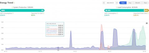
Every day changing from around in between 0430 till 0630 a load is drawn usually between 0,5 and 1 kWh and it just annoys me now:)
The rest of the day the system is spot on with no draw from the grid at all.
The wierd thing is that the majority of the day the system works, just not that short period in the morning......
Skærmbillede 2022-08-30 084157.jpg

Skærmbillede 2022-08-30 084404.jpg
 
Last edited:
That would annoy me too. Any idea what the peaks are overnight (2-3am)? It's like it's not kicking in for one of those spikes later in the morning. What's your battery charge by that time of day?
 
That would annoy me too. Any idea what the peaks are overnight (2-3am)? It's like it's not kicking in for one of those spikes later in the morning. What's your battery charge by that time of day?
At this time a year around 60-70% (20kWh capacity)
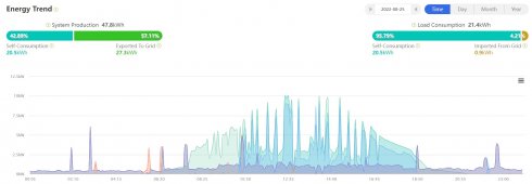
The time it happens is usually between 0430 and 0630 no matter the load. Tried switching all consumers off one at a time till everything was off and the system still did this.
Sometimes it happens during the day but only maybe 50w over max 5 min.
 
Screenshot 2022-08-31 at 17.44.39.png
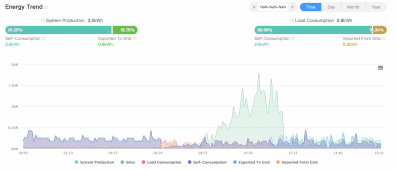
similar here, 6-8am ish for me. My panels are on the south side so don't do anything useful until mid morning.

I suspect this is something to do with the panels starting to show a voltage near or above the 150v minimum and the inverter being in a transitional state where a limit has not been reached. Most likely something that can be fixed with a firmware update, if we can get any one from Growatt to take notice. Perhaps with a three like this and others chiming in we can give them some evidence. I have a 90% full battery in the example above at 6:20am ish so no need for the grid. Away at the mo but there is an ATS waiting for me at home to practice some off grid living.
 
View attachment 109547
similar here, 6-8am ish for me. My panels are on the south side so don't do anything useful until mid morning.

I suspect this is something to do with the panels starting to show a voltage near or above the 150v minimum and the inverter being in a transitional state where a limit has not been reached. Most likely something that can be fixed with a firmware update, if we can get any one from Growatt to take notice. Perhaps with a three like this and others chiming in we can give them some evidence. I have a 90% full battery in the example above at 6:20am ish so no need for the grid. Away at the mo but there is an ATS waiting for me at home to practice some off grid living.
That is a very plausible theory, I have half my panels east and half west. Didn´t think of it that way.
I will try to test by coupling out my water heater in the morning and as many consumers as possible and wait a couple of hours after the panels kick in to re-engage the consumers.
 
Done and working. The ct clamp is gone and the meter is installed And it’s so much better :) often the in-home display shows zero now as opposed to 150w with the rubbish clamp, sometimes it fluctuates out for a few seconds, but then comes back under control. Usually when a load is starting or stopping.
Hi, apologies- I am new to this forum. Just got a Growatt system installed but I have the CT clamp and the same issues described here. Does the meter connect in line on the AC cable between the inverter and the main consumer unit? Many thanks
 
Hi, apologies- I am new to this forum. Just got a Growatt system installed but I have the CT clamp and the same issues described here. Does the meter connect in line on the AC cable between the inverter and the main consumer unit? Many thanks
It's earlier in the chain, between the incoming
Hi, apologies- I am new to this forum. Just got a Growatt system installed but I have the CT clamp and the same issues described here. Does the meter connect in line on the AC cable between the inverter and the main consumer unit? Many thanks
A bit earlier in the chain, between the main (dno supplied) meter and where the solar comes in.
 
View attachment 109547
similar here, 6-8am ish for me. My panels are on the south side so don't do anything useful until mid morning.

I suspect this is something to do with the panels starting to show a voltage near or above the 150v minimum and the inverter being in a transitional state where a limit has not been reached. Most likely something that can be fixed with a firmware update, if we can get any one from Growatt to take notice. Perhaps with a three like this and others chiming in we can give them some evidence. I have a 90% full battery in the example above at 6:20am ish so no need for the grid. Away at the mo but there is an ATS waiting for me at home to practice some off grid living.
This sounds like the same type of situation that was happening with the Schneider inverters. When the sun would come out in the morning and charging began the inverter would stop supplying the load and instead start to only charge. The Schneider would have to be cycled on/off to begin supplying the load again. I think that was only happening when the Schneider was in grid tie mode.. however the growatt is atleast restarting to supply the load on its own.. from both of your graphs the growatts completely stop supplying the load and slowly resume supplying the load. For some reason the charge controller is becoming prioritized to charge the battery over supplying the load. I suspect possibly when the battery becomes full it is resuming fully supplying the load.
 
It's earlier in the chain, between the incoming

A bit earlier in the chain, between the main (dno supplied) meter and where the solar comes in.
Can you explain more, My installer put My Eastron 230 V2 (in mini CU) after 100A breaker and just before my solar pv is one one 20A MCB and AC Inverter/Battery on another 16A MCB, in the mini CU with tails from the Henley block, seperate from Main CU which also has seperate tails from Henley block....

where should the Eastron 230 be connected?

Have taken the mini CU cover off to see what is connected....

Eastron Meter has Pins 5 white/orange 485A and 6 brown 485B connected by RJ45 cable but hanging loose (The Solax X1 AC3.6 manual states for Meter connection to Eastron SDM 230 is Pins 7 white/orange and 8 Brown of RJ45 pinout. I have a feeling it is not connected up correctly plus no RJ45 cable connected to inverter connector, hanging loose., Inverter connector is used by CT ethernet RJ45 on Grid live.

Just found CT from Inverter Solax X1 AC 3.6kw to Grid Live cable (after DNO Meter) but before the Henley Block which is giving my readings.... which is like 100w above as in the thread... nearly 2kw daily for 24 hr period

How should the Eastron V2 be wired up..... https://www.jwsmartmeters.co.uk/wp-content/uploads/2018/02/Eastron-SDM230-Modbus-v2_User-Manual.pdf so I can check why it is not being used... the box the Eastron meter v2 came in states for Solax and Growatt inverters...

This has all happened after my solax AC inverter and Master and slave 11.6kw batteries were installed last month. Electric has been halved
and cost and very happy, but came along this thread and started to investigate....

Any help is greatly appreciated.
 
Hard to tell from your description, but sounds about right from memory, although if the data cable is hanging loose doesn't
 
Can you explain more, My installer put My Eastron 230 V2 (in mini CU) after 100A breaker and just before my solar pv is one one 20A MCB and AC Inverter/Battery on another 16A MCB, in the mini CU with tails from the Henley block, seperate from Main CU which also has seperate tails from Henley block....

where should the Eastron 230 be connected?

Have taken the mini CU cover off to see what is connected....

Eastron Meter has Pins 5 white/orange 485A and 6 brown 485B connected by RJ45 cable but hanging loose (The Solax X1 AC3.6 manual states for Meter connection to Eastron SDM 230 is Pins 7 white/orange and 8 Brown of RJ45 pinout. I have a feeling it is not connected up correctly plus no RJ45 cable connected to inverter connector, hanging loose., Inverter connector is used by CT ethernet RJ45 on Grid live.

Just found CT from Inverter Solax X1 AC 3.6kw to Grid Live cable (after DNO Meter) but before the Henley Block which is giving my readings.... which is like 100w above as in the thread... nearly 2kw daily for 24 hr period

How should the Eastron V2 be wired up..... https://www.jwsmartmeters.co.uk/wp-content/uploads/2018/02/Eastron-SDM230-Modbus-v2_User-Manual.pdf so I can check why it is not being used... the box the Eastron meter v2 came in states for Solax and Growatt inverters...

This has all happened after my solax AC inverter and Master and slave 11.6kw batteries were installed last month. Electric has been halved
and cost and very happy, but came along this thread and started to investigate....

Any help is greatly appreciated.
not sure about solax, but Growatt has an rj45 port called ct and an rj45 called meter, plugging an rj45 into the meter port and connecting to the estron meter. Think it uses modbus protocol. The meter should be connected your side of the main utility meter. So that the inverter can capture all import and export and balance the usage to as close to 0w as possible. Estron is accurate to 20ish watts, ct clamp was accurate to 100ish watts in my tests.
 
Hi guys it has Eastron SDM 230 meter, the cable to the inverter is not connected, I somehow have a RJ45 connector and the cable goes to the
Main Grid Live in meter cabinet.... been reading the manual, and tried to use the cable from Eastron but when connected and inverter restarted
and change the CT/Meter to Meter from CT when working... the Inverter screen say Meter Fault with Red LED Triangle on inverter screen lit.

Change back to the CT clamp and RJ45 connector to inverter and all working again....

Will investigate the Connections from the Eastron at later date... and why it is not operational, it does have numbers on the box, when you
scroll through the enter button.... but I don't know if it all working correctly or if the cable from Eastron meter to the inverter should be connected
at all.
 
sounds like you have a CT clamp at present, and some one tried installing a Eastron 230 meter but didn't use it, there are various versions so maybe it was the wrong one, or they ran out of time configuring and ended up with the CT.
 
The box states for Solax/Growatt for the Eastron meter.. just looking at the Solax cloud and my solax X1 boost 3.6kw and 5.2kw is working fine today to charge the batteries so system is working... just need some time to get someone to look at the Eastron meter connections in the mini CU.

My mini cu is connected only too solar PV is on mcbo 20Aand next is solax battery mcbo 16A to 100A breaker connected via meter tails to the henley block... in main DNO meter cabinet on outside of the garage, batteries and inverters both solax on inside of garage wall 2m away from
the outside meter cabinet.
 
My Eastron SDM 230 V2


How should you refer to the L In and N In on the top of the meter, will that be connected to the 100A breaker with meter tails, or is that the input from the inverter via its connection to the RCBO 16A breaker in the mini CU....

also the L Out and N Out is that for the solax battery inverters RCBO breaker (will need to verify the wiring... it could be a good working Eastron meter if wired incorrectly)...

the RJ45 cable has been confirmed with the correct pinouts from the solax manual using pin 7 white/brown to Pin 5 on Eastron 485A and pin 8 brown to pin 6 485B on Eastron meter, taken the cover off the 4way mini CU....

Any help in identifying the wiring connections of the above Eastron Meter greatly appreciated..... I need to know if it is wired correctly before more
expense is made to get a qualified electrician to check... as my installer says the system is working fine... but as I do not understand is why then
just leave the eastron meter in use unconnected...
 
Does the henley block split the power cables to the the house and the garage ? the meter needs to be before it splits to the house, so directly after the DNO meter. Possibly with isolator switch in-between.
 
The house CU is next to my 6 way mini CU for 100A breaker, connected to Eastron meter then connected (not clear where the cables go from Eastron Out bottom of it to solar rcbo and battery rcbo , also another mini one way EV charger Hypervolt all on garage wall, the main Electric cabinet is on the outside through the wall.

Each are connected on meter tails from Henley Block which is connected to Ocotpus Go Main Meter then to 100A isolator which connected to Main DNO 100A Fuse.

To be honest I am no electrician, and with no room in the outside electric meter cabinet, which also has clamp for iboost +, clamp for EV and
clamp for Solax battery on the main grid live.... plus large henley block two in and 6 out (can tell by the different size cables, in looks like 25mm and
6 out could be 16mm or 16mm in and 6 x 10mm out who knows)

yes i can see how you say the eastron would be situated, placed for connection to oversee the whole house grid... to work effectivel and correctly.
 
Hello everybody, my inverter Growatt sph 10000tl3 bh-up have problem. Permanently reflux to grid over 60 watts, all day, all night, from battery. Can you help me please? Thanks...
 
I have found *a* solution to this which doesn't involve switching out the CT Clamp. Though it's not a solution for the faint of heart. My SPH-5000 was doing this (consuming a small amount all night at low loads) despite having loads of battery capacity.

I adjusted the Inverter to switch to "Grid First" mode each night at about 5PM, and turn back to the default "Load First" at 6AM. This can be done from the console. Then I use a script on a Raspberry PI to write to the RS232 interface and set the % power out register using the Growatt Modbus protocol. This is the same register you see in the display when setting the start/end time of "Grid First" mode. That script runs every 5 seconds.

It's not perfect, but I have a "minimum value of about 8% which covers all my night time loads, then via separate CT clamps I monitor power usage, and solar input and adjust. It doesn't react as fast as the CT clamp, but I set some headroom to adjust for that. If you didn't want to use the script you could use a later time of 10PM -6AM and hard code the value to the base load of your house plus a little for lights, or fridges turning on and off, and set that manually on the console.

I use the script becasue I'm also on a 1/2 hourly wholesale feed in tariff. So when the price goes up in the evening, and it can go *high*, the script pushes the output to 100% and I'm paid good money for electricity I saved earlier in the day. That was my main point in building this solution, but solving the "always pulling a little from the grid" problem was a happy side effect.
 
Back
Top