diy solar

diy solar

How to setup right parameters JK BMS

kta22

New Member
Joined
Apr 26, 2022
Messages
21
Hello,

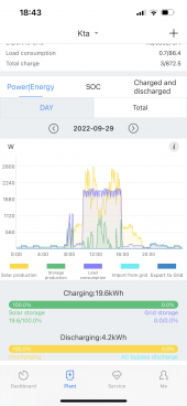
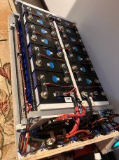
I’ve got this configuration ( Eve L280K + JK BMS + growatt inverter). I’ve setup OVP=3.345V and OVPR=3.320V and charging curent 15A. Everyhing works well(Even charging my electric Kona from the battery. My questions are related to OVP and OVPR values, because up to 90% the BMS is charging constantly with ~900W, but above 90% and up to 100% begins kind of oscilation phase with a 2-3min on and 10min off up to 100%. Is it normal and harm batteries somehow? How to avoid these oscillations ?

Thabks
 

Attachments

  • 04E34B5D-EDFB-455E-86BF-DB5D24D7F57A.png
    04E34B5D-EDFB-455E-86BF-DB5D24D7F57A.png
    664.8 KB · Views: 89
  • A6A78F7B-585E-4CFA-9CCE-0CF8627F40C6.jpeg
    A6A78F7B-585E-4CFA-9CCE-0CF8627F40C6.jpeg
    220.6 KB · Views: 96
Based on the limited information provided, it seems like your BMS is cycling on and off. This should not happen, your Inverter settings are supposed to be the primary means of charge control. The BMS is supposed to be the last and final level of cell protection before the voltage goes so far out of range that the cells are permanently damaged.

OVP and OVPR you are referring to are your BMS settings? The values given are incorrect. For LFP chemistry Over Voltage Protection should be set at 3.6V to 3.7V and Over Voltage Protection Resume should be set at whatever the OVP is minus about 0.1V.
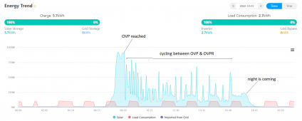
OVP & OVPR yes, to the JK BMS. So, when battery is discharged it will draw power constantly up to OVP (3.345V ~ close to 90%) and afterwards cycles between OVP and OVPR begin. Growatt inverter is supplying the battery with 55.1V charging & floating and the rest of the job is done basically by BMS.
 

Attachments

  • Capture1.PNG
    Capture1.PNG
    70.8 KB · Views: 24
When battery is discharged it will draw power constantly up to OVP (3.345V ~ close to 90%)
When a battery is discharging it will draw voltage down and the Inverter should be set to stop Inverting at about 46V to 48V (2.875V to 3.0V per cell) The UVP and UVPR are used to set the BMS to shut down on Under Voltage so as not to let the battery be discharged until damage occurs. It should be set at about 2.6V to 2.7V and UVPR should be set about 0.1V higher.
and afterwards cycles between OVP and OVPR begin.
The BMS is not supposed to CYCLE, its a protection device not a control device. The concept is the same as the breakers in your load panel. They don't cycle on and off, you turn your appliances on and off as needed. The breaker only TRIPS if there is a short circuit.
The Inverter is the means of control, its the device that cycles between battery Charging and supplying power (Inverting/Discharging batteries.)
Growatt inverter is supplying the battery with 55.1V charging & floating
55.1V is OK for charging its on the low side but best to leave it alone for now and get the BMS set up correctly. At present the BMS is incorrect.
and the rest of the job is done basically by BMS.
I don't know what you mean by rest of the job?? I'll say it again, the BMS has no other job than to be the last and final protection device to prevent permanent damage to the battery cells. Under normal circumstances the Inverter settings are chosen so the battery cells never experience either too high or too low a voltage such that the BMS has to disconnect.
 
Last edited:
Here are my settings which work perfectly fine on each pack in my bank.
Note I am running a Midnite Classic SCC & Samlex EVO Inverter at 24V, so double the numbers for 48V on the charge settings.

Pending on model of BMS, set the "Continued Charge Current" to 140A (0.5C of cell.)

Latest Android App here: https://www.pgyer.com/Cfq3
* TRANSLATE from Simplified Chinese with your browser,

App information​

size 15.1 MB
Update time 1 hour ago
version 4.9.1 (build 65)
Developers Zhang peng

Alt Source for App (bit of delay getting there...)
 
When a battery is discharging it will draw voltage down and the Inverter should be set to stop Inverting at about 46V to 48V (2.875V to 3.0V per cell) The UVP and UVPR are used to set the BMS to shut down on Under Voltage so as not to let the battery be discharged until damage occurs. It should be set at about 2.6V to 2.7V and UVPR should be set about 0.1V higher.

The BMS is not supposed to CYCLE, its a protection device not a control device. The concept is the same as the breakers in your load panel. They don't cycle on and off, you turn your appliances on and off as needed. The breaker only TRIPS if there is a short circuit.
The Inverter is the means of control, its the device that cycles between battery Charging and supplying power (Inverting/Discharging batteries.)

55.1V is OK for charging its on the low side but best to leave it alone for now and get the BMS set up correctly. At present the BMS is incorrect.

I don't know what you mean by rest of the job?? I'll say it again, the BMS has no other job than to be the last and final protection device to prevent permanent damage to the battery cells. Under normal circumstances the Inverter settings are chosen so the battery cells never experience either too high or too low a voltage such that the BMS has to disconnect.
Thanks for support, you're right, it's more clear now for me!
 
Thanks for support, you're right, it's more clear now for me!

Here are my settings which work perfectly fine on each pack in my bank.
Note I am running a Midnite Classic SCC & Samlex EVO Inverter at 24V, so double the numbers for 48V on the charge settings.

Pending on model of BMS, set the "Continued Charge Current" to 140A (0.5C of cell.)

Latest Android App here: https://www.pgyer.com/Cfq3
* TRANSLATE from Simplified Chinese with your browser,

App information​

size 15.1 MB
Update time 1 hour ago
version 4.9.1 (build 65)
Developers Zhang peng

Alt Source for App (bit of delay getting there...)
Thanks!
 
A few things that do NEED Clarification for your own sanity and because there are LEADisms and Wives Tales associated with them due to misunderstandings.

LFP has a Very Flat Voltage curve and is even a bit peculiar when it comes to Lithium Based Batteries. ALL Lithium IS Millivolt & Milliohm sensitive, unlike FLA (Lead Acid) which is "Brute Force" old tech.

The "Allowable Voltage Range" for LFP starts at 2.500 and ends at 3.650 Volts per cell. There is No Harm/Damage cause when the cells remain in that range. Go Above or Below and you're causing harm. LFP Has a Low Internal Resistance compared to others and as such can put out a LOT of juice in a burst.

The "Working Voltage Range" is 3.000-3.400 Volts per cell, yes, that's right, ALL the deliverable AH is from that tiny 0.400V Range (280AH from a 280AH Cell.) for Grade A Nominal Voltage is always indicated as 3.200 Volts which IS 50% SOC.

By Charging to 3.425Vpc 54.8V (48V System) you are just over the top edge and allowing for the cells to settle (LFP Always settles a bit), this also prevents any Cell from becoming a Runner and going high. You can safely discharge to 2.900Vpc 46.4V again without issues and never ever see a "Runner Cell" which can go low fast. MAKE SURE Your Inverter has a Low Voltage Cutoff @ 2.650Vpc / 42.4V

That notion of keeping charge between 20%-80% or some say 10%-90% is under the "Assumption" of using the Allowable Voltage Range.

The only time to take the cells up to 3.600-3.650 is when Top Balancing them to "activate" the cells fully after long term storage from shipping.

Depending on your Solar Charge Controller (Terms vary between brands (what a PITA) there may be an EndAmps / Tailcurrent setting. Once the Endamps is reached, the SCC will change from Constant Current to Constant Voltage Variable Current (FLOAT) which will reduce amps as the cells fill up and increase resistance. This fully saturates the cells to THAT Voltage point ensuring you have them topped off and fully charged to capacity.

In case you cannot see my signature, check these links out.
https://diysolarforum.com/resources/luyuan-tech-basic-lifepo4-guide.151/ More info that is handy within.

Hope it helps, Good Luck
Steve
Thanks for useful information.
 
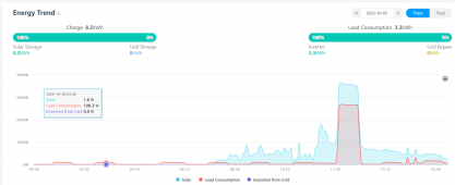
Hello to all, seems that after BMS & Growatt parameters update(~11:00) on your recommendation, my system start to work as I was expected from the begining. Thanks
 

Attachments

  • Capture.PNG
    Capture.PNG
    57.8 KB · Views: 35
Hello to all, seems that after BMS & Growatt parameters update(~11:00) on your recommendation, my system start to work as I was expected from the begining. Thanks
Hi,
Can you help me here,with Growatt side parameters ?Thank you in advance!
 
Back
Top