diy solar

diy solar

Hydraulic crimping and soldering - Sol Ark 15k DC wiring

byteharmony

Sunny side up please.
Joined
Jul 29, 2022
Messages
233
Location
Milwaukee
Here is the process I'm considering for connecting the wires to the lugs:
  1. Put a lug in hydraulic crimper
  2. Strip and insert 2 tinned 10 AWG stranded THHN wires into a tinned lug
  3. solder wires to the lug - torch?
  4. immediately crimp the wires after removing heat
  5. release crimper and allow everything to cool
  6. slide on shrink wrap and shrink with heat gun.
Is there a better way to connect two 10 AWG wires to a single lug?

Background:
I had fun this morning testing lugs with the Sol Ark 15k now beautifully mounted on my basement wall.
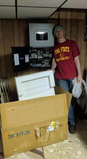
Sol Ark 15k unboxed 2022-12.jpg

I have 2 very large spools of 10 AWG THHN for my solar job (a gift, thanks Dad).

I'm going to have a VERY large network of DIY 18650 cells.

Thinking about using two 10 AWG wires in a single 8 AWG 5/16" lug. Lugs back to back against the sol ark battery terminal, then spaced by a copper 3/8 pipe that is cut to allow enough room for another back to back lug set before the nut.

With this setup I expect the following power calcs:

Total 10 AWG wires per battery terminal: 8
at 30 AMPS / 10 AWG wire, total current: 240 A
total terminals per each polarity: 2
Max current: 480 A
Sol Ark limit 375 A
# of wires that could fail without going over 30 A per wire: 3.5 wires
Reduce current to increase safe failure risk and reduce load on Sol Ark
Increase wire failure to 4, 2 failures per set of wire on each terminal: 4*30 = 120 A
480 A - 120 A = 360 A (96% of max charging power able to be delivered by the Sol Ark 15k)
360 A / 16 wires = 22.5 A / 10 AWG wire

I'm also planning on using a Trophy 48V100E-1 in my lawn tractor that will be connected with a different set of wiring to control voltage over a large distance.

Looking forward to summer everyone!
Will be using the Trophy exclusively at least until the first 18650 DIY is ready.

design for each 18650 battery
280 cells, 14s, BD6A17S6P JKBMS, 30 AMP Class T fuse

FYI, yes I know the top clearance does not meet with Sol Ark spec... this will be addressed before the Sol Ark is turned on.
 
friends raise concerns about heat on crimper.

Suggestion:
1. insert wires in lug, pin lug against cement floor.
2. Torch lug and fill with solder
3. Allow to cool
4. Crimp
 
IMO, you should avoid solder. Use quality crimping (COPPER plugs not alu) with enough pressure and heatshrink to cover any visible copper and plugs. Do not use alu cable, only copper.

Use ferules on each of the smaller cables as well.
 
IMO, you should avoid solder. Use quality crimping (COPPER plugs not alu) with enough pressure and heatshrink to cover any visible copper and plugs. Do not use alu cable, only copper.

Use ferules on each of the smaller cables as well.
Thanks for the input, I considered that. I have no experiance with this.

The wire is stranded copper, the lugs are copper. I think the hydraulic crimper will crush the metal together so hard it will bond it. The copper has better conductivity than solder. I believe @Will Prowse spoke in a video about solder crimped connections impressing him. My logic and your perspective would say it's not as wise to do both.

Thoughts anyone?
 
Don't solder then crimp, that's a nearly guaranteed failure.

Just crimp them using quality ring terminals/lugs and a good crimper.

Better advice is to use bus bars as the Lord intended.
Run one large cable (or two because Sol-Ark has 2 and 4/0x2 is needed for 375 amps) into the SolArk down the the bus bar, then all 40,000 8 awg battery wires can connect to the bus bar in single properly sized ring terminals with just crimps.

Also, that Trophy battery looks to have a 100 amp limit, make sure you program your battery draw limit into the inverter. It's going to be severely limited (not "limitless" ?) when running on just the one Trophy.
 
When I was working at a heavy equipment rental/repair company we would crimp then solder then put heat shrink on the connection other places I’ve seen crimp/shrink or strait solder socket type if you have a good crimp with heat shrink it should be just fine. Soldering can be compromised if cables get hot and cause problems also more time consuming
 
If you get a good crimp solder can't improve it.
But I really think you should re-evaluate your plan to use multiple parallel THHN cables instead of something right. I can't believe you can afford a Sol-Ark but can't get the proper cables.
I'd check with someone who knows, but I don't think that would be approved by any inspector.
You would be surprised where solder will sweat into it will seal air tight
 
Thanks everyone for the feedback, please add anything else you can think of, I love reading this stuff!!!


Don't solder then crimp, that's a nearly guaranteed failure.

Just crimp them using quality ring terminals/lugs and a good crimper.

Better advice is to use bus bars as the Lord intended.
Run one large cable (or two because Sol-Ark has 2 and 4/0x2 is needed for 375 amps) into the SolArk down the the bus bar, then all 40,000 8 awg battery wires can connect to the bus bar in single properly sized ring terminals with just crimps.

I am largely creating a bus bar out of the huge connections the sol ark gives me.

Also, that Trophy battery looks to have a 100 amp limit, make sure you program your battery draw limit into the inverter. It's going to be severely limited (not "limitless" ?) when running on just the one Trophy.
yes, 160 A per each terminal.

At first I'll need to limit the draw and charge, as I get more lithium. I plan on buying it by the pallet at battery hookup using their auction :-D.
When I was working at a heavy equipment rental/repair company we would crimp then solder then put heat shrink on the connection other places I’ve seen crimp/shrink or strait solder socket type if you have a good crimp with heat shrink it should be just fine. Soldering can be compromised if cables get hot and cause problems also more time consuming
Interesting. Perhaps this is what @Will Prowse referenced liking?

If you get a good crimp solder can't improve it.
But I really think you should re-evaluate your plan to use multiple parallel THHN cables instead of something right. I can't believe you can afford a Sol-Ark but can't get the proper cables.
I'd check with someone who knows, but I don't think that would be approved by any inspector.
Thanks, yes, I can afford anything I want at this point in life and I am grateful that most of what I want is to dream about cost effective ways to do fun things like build my sol ark solar system.

I plan on changing my 0/2 AWG approved wire plans to 1 AWG to comply with the NEC AMP chart for the 100 A max draw the breaker on the Trophy which will be in place when I attempt to pass inspection. Who knows where I'll go from that point forward.

You would be surprised where solder will sweat into it will seal air tight

So you think it would be best to crimp, then heat with a torch and solder the wires? That makes sense to me, the solder providing additional welding strength and conductivity where any copper isn't smashed together.

Thanks everyone for the great feedback!!!

Happy New Year!!!
 
As others have noted. If you use a decent crimper and quality copper crimps there should be no need to solder.

If you have a crappy crimper / low quality crimps then soldering can add to the electrical strength (crimp first).

BUT

If you have a high vibration (mobile) application then the solder can wick under the cable insulation and cause a stress point leading to a fatigue failure under the insulation and heartache. There's a reason vehicle wiring is exclusively crimped (it's faster too).

Long (long) ago when I was an RN apprentice, we had to do soldering exercises involving lots of small wires, bucket terminals and neoprene sleeves. Woe betide you if the instructor discovered wicked connections, rip it all apart and start again.

We also learned how to "lace" wire looms, done properly it looks fantastic!

Cable_lacing_close-up.jpg
 
Last edited:
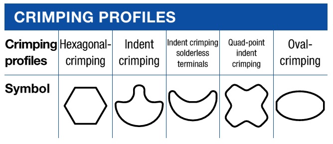
An interesting article on cable crimping https://www.powerandcables.com/cable-lugs-crimps-hexagonal-v-indent-methods-of-crimping/

Which is your favourite profile?

Crimping-Profile-Chart.jpg
Loved this read.

Also found a number of posts very helpful. At the end, the information that the solder sweated into the joint causes the joint to be brittle which may result in a reduction of conductifity and perhaps at some point, joint failure ruled my day.

After getting the info here I searched a few topics I otherwise wouldn't and found this form that gave me further great info:

Thanks everyone!!!
 
all methods have good and bad points but in a non lab environment with average equipment all methods done correctly will give good results at least I hope so I have 8 bms that came with soldered only cables (overkill/Jbd)
 
Loved this read.

Also found a number of posts very helpful. At the end, the information that the solder sweated into the joint causes the joint to be brittle which may result in a reduction of conductifity and perhaps at some point, joint failure ruled my day.

That is correct, the cable will be compromised right at the point where it enters the lug.
After getting the info here I searched a few topics I otherwise wouldn't and found this form that gave me further great info:

Thanks everyone!!!
I've commented on soldered vs crimped terminals. https://diysolarforum.com/threads/c...les-without-special-tools-0.48122/post-612673

You look to be a young fella, must be smart as you went to ISU (any of my brothers and sisters plus my son graduated from ISU) and have a long journey ahead in life. If you are serious about DIY solar systems with batteries, buy a hydraulic crimper.
 
all methods have good and bad points but in a non lab environment with average equipment all methods done correctly will give good results at least I hope so I have 8 bms that came with soldered only cables (overkill/Jbd)
From what I read you're fine as long as you support those soldered cables to avoid movement on the brittle solder.

That is correct, the cable will be compromised right at the point where it enters the lug.

I've commented on soldered vs crimped terminals. https://diysolarforum.com/threads/c...les-without-special-tools-0.48122/post-612673

You look to be a young fella, must be smart as you went to ISU (any of my brothers and sisters plus my son graduated from ISU) and have a long journey ahead in life. If you are serious about DIY solar systems with batteries, buy a hydraulic crimper.
So kind, thank you.

I purchased a hex hydraulic crimper long ago and am looking forward to using it on this solar system as well as many other applications.

From a scientific perspective I'd propose it would be best to have the end of the lug being bolted open and sweat solder into that end with a heat sync on the other wire side to avoid wicking into the area that risks movement (can't be brittle). That would reduce air where the solder displaces it, creates brittle areas only where the metal of the lug reinforces the part and increases conductivity. Don't see that product, maybe a reason for that. Certainly more work adding solder.

Perhaps due to the fact that the cold weld is better? Looking forward to experience with that and many more years of solar joy!

Thanks all.
 
If you get a good crimp solder can't improve it.
But I really think you should re-evaluate your plan to use multiple parallel THHN cables instead of something right. I can't believe you can afford a Sol-Ark but can't get the proper cables.
I'd check with someone who knows, but I don't think that would be approved by any inspector.
Not code compliant to parallel small wires. Any inspector would red tag you for what you are proposing; as others have stated just get the correct wire and terminals and don't solder.
 
From what I read you're fine as long as you support those soldered cables to avoid movement on the brittle solder.


So kind, thank you.

I purchased a hex hydraulic crimper long ago and am looking forward to using it on this solar system as well as many other applications.

From a scientific perspective I'd propose it would be best to have the end of the lug being bolted open and sweat solder into that end with a heat sync on the other wire side to avoid wicking into the area that risks movement (can't be brittle). That would reduce air where the solder displaces it, creates brittle areas only where the metal of the lug reinforces the part and increases conductivity. Don't see that product, maybe a reason for that. Certainly more work adding solder.

Perhaps due to the fact that the cold weld is better? Looking forward to experience with that and many more years of solar joy!

Thanks all.
It looks like you're really sold on the idea of soldering.
Don't forget that you should clean the flux off.
Please post some pictures of the insulation on that THHN when you're done. I'm afraid it will suffer a little from the heat.
I'd also like to see the details of a heat sink good enough to keep solder from wicking up the cable. One of those would be handy to have.
Good luck.
 
From what I read you're fine as long as you support those soldered cables to avoid movement on the brittle solder.

The issue is capillary action of the flux and solder, it wicks far down the cable.

So kind, thank you.

You are welcome, I hope you have a bright future.
I purchased a hex hydraulic crimper long ago and am looking forward to using it on this solar system as well as many other applications.

You are off on the right step. If the hydraulic crimper is used and makes a proper crimp, the solder won't flow down into the terminal. It should be that tight. Using terminals that are not correct for the wire size is an example of not having a proper crimp and some will attempt solder to tighten such a connection. When the connection heats up and the solder melts, the cable can pull out and create a short.

That's just an example, not saying you doing it. Proper hydraulic crimps will not allow solder up into the terminal so it is a waste of time and effort.

From a scientific perspective I'd propose it would be best to have the end of the lug being bolted open and sweat solder into that end with a heat sync on the other wire side to avoid wicking into the area that risks movement (can't be brittle). That would reduce air where the solder displaces it, creates brittle areas only where the metal of the lug reinforces the part and increases conductivity. Don't see that product, maybe a reason for that. Certainly more work adding solder.

Solder has a place, usually when sweating plumbing fittings. Different kind of solder.

Other than that, the only place it should be used is on circuit boards, and those do have problems over time with solder cracks leading to poor connections. I've repaired many circuit boards over the years with my soldering station.

Even on small wires under 10AWG, I have moved away from solder practices I used 30 years ago and use barrel crimp connectors on everything now.

Perhaps due to the fact that the cold weld is better? Looking forward to experience with that and many more years of solar joy!

Thanks all.
Cold weld is the best. Airtight, no issues with flux, excellent conductivity.
 
Back
Top