diy solar

diy solar

isolation of battery to inverter comms

Pretty wild having a 48V battery biased to some -150 or -200V with respect to earth.
Is it floating, just charged up? Would a high impedance pull it back to relatively safe voltages?
Yes, it surprised me to see that voltage on the battery, as I often touch my battery bus bars when it's all running and I'm still here!!

So, I suspected it is just floating and attempted to measure the current that would flow through a 100R resistor. All I got was a one off brief spark and zero current measurable through the resistor. But, in the process I managed to destroy another CANbus adapter, despite it not being attached to the Solis - puzzling as it is only connected to the battery -ve directly and the 5V +ve via the buck converter from battery +ve. I would have done more testing, but didn't want to zap anything else (including me!).

All a bit puzzling really - but maybe others who know more about the inverter's DC bus might chip in. @RCinFLA shared a nice diagram of how these inverters work (see https://diysolarforum.com/threads/t...ttery-and-inverter-to-mains.74684/post-946431). All that shows is a buck converter between the dc bus and the battery, so from that I'd deduce that whatever the 'ground' of the dc bus is using would get used for the -ve battery. Which sort of fits with it being at -195V, but if the DC Bus is floating wrt earth then I guess it doesn't matter.

You checked battery bias vs. ground, did you check logic/comms?
No, I managed to zap an adapter without it connected on the comms side, so didn't feel there was any gain to check more :LOL:

If there is capacitance to a circuit, even though there is galvanic isolation, when common-mode is suddenly applied it forces in current. Which you may be able to measure, or measure voltage rise time and capacitance to determine current

ICs often spec not to drive inputs more than +/-0.4V relative to rails, but if they can have sufficient series resistance it protects them. Not so practical for fast outputs, but at remote inputs would limit current. Otherwise, when a device is unpowered the data lines can try to bring up its power rails through ESD protection diodes.
Yes, that makes sense. If I had more time (and spare components) I'd try putting my scope on it, just to understand it better... But the scope is grounded and Solar Guppy (who has a Solis) had previously said...
it is important that you do DO NOT GROUND PV or BATTERY +/- or you will permanently damage the unit
 
We usually don't ground PV. Some GT PV inverters grounded PV- through a fuse, called it ground fault detection.

Batteries often do get one side grounded. 12V house battery systems in vehicles, of course.
Midnight says only ground is to be through their ground fault detection breaker.
It will depend on brand, should be documented.

Using a scope, differential probe or math on two single-ended probes is one way.
I've bought myself Tek HV diff probe and one of those boxed LV probes. When lower prices showed up.
 
I managed to destroy another CANbus adapter, despite it not being attached to the Solis - puzzling as it is only connected to the battery -ve directly and the 5V +ve via the buck converter from battery +ve.
Where does the output of canbus adapter connects to?
 
All Solis Hybrid's are non-isolated to the battery connections similar to the PV connections. So having a power supply off the battery will have significant voltage potential to ground. I own the High Voltage Hybrid, but the Low Voltage Hybrids are the same architecture
 
All Solis Hybrid's are non-isolated to the battery connections
Do you have a schematic of this architecture you could share? I am curious why 50V to 400V DC-DC converter is not isolated. It should be using HF ferrite transformer which is galvanic isolated part.
 
Do you have a schematic of this architecture you could share? I am curious why 50V to 400V DC-DC converter is not isolated. It should be using HF ferrite transformer which is galvanic isolated part.

Non-Isolated designs can be more energy efficient, and from a design stand point could be implementing the same architecture used for the PV boost stage as well. I do not have schematics but if you review the line diagrams for the Solis ( S5 , S6 and 5G ) in the manuals shows no connects to ground, the battery inputs are dedicated.
 
Where does the output of canbus adapter connects to?
Output of Canbus adapter (indirectly from the BMS) goes to battery comms input of the Solis (for the inverter to receive SOC info etc.)
 
All Solis Hybrid's are non-isolated to the battery connections similar to the PV connections. So having a power supply off the battery will have significant voltage potential to ground
Thanks - that confirms what I am measuring.
 
Output of Canbus adapter (indirectly from the BMS) goes to battery comms input of the Solis (for the inverter to receive SOC info etc.)
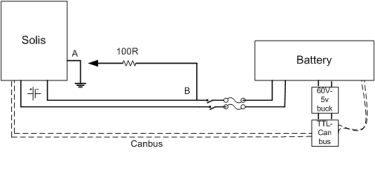
Could you make a diagram of Solis, BMS, battery, CAN connections and where exactly did you connect 100R resistor with measurement equipment setup? I suspect inverter EMI filter caps could be biasing your battery with relation to ground. I was dealing with similar issue with Growatt 5000es recently.
 
Here's a diagram. Voltage between points A and B is about 190V, as detailed above (B being the battery -ve, which is -190V below ground level when measured with voltmeter). Connecting an ammeter and 100R resistor across those points triggered the small spark, but no current detectable on ammeter. But doing that zapped the TTL-Canbus adapter, despite the CAN connection being disconnected from the Solis at the time. As originally posted, re-connecting the batteries via the battery disconnector has occasionally zapped the CANbus adapter when it was connected to the Solis.

1702985545026.png
 
This is not a capacitive couple issue, it is a typology limitation for your way of implementing communications. You will have 1/2 mains voltage typically on the battery terminals as measured to ground as it is a non-isolated design. Your canbus needs to be fully galvanically isolated, no if , ands or butts on this.

You are very luck you didn't fail the inverter by placing components on the battery terminals to ground, stop playing around with this or you risk losing the inverter
Thanks, I agree re not do any more tests like the current test one (don't want to lose the inverter or more)... and that makes sense re the mains voltage on the battery side. I will be swapping over to using a galvanically isolated CANBus adapter very soon.

But what is puzzling is there are no components (apart from the one-off 100R resistor test) on the battery terminals that are connected to ground.

The 48-60V to 5V buck converter that supplies the ESP32 and CANBus adapter are connected to the battery terminals themselves, so the -ve of the CANBus adapter is connected to the -ve of the battery and nothing else - so it was / is just floating and working well for over a year. I would assume that is the same architecture as all commercially available battery racks, as they don't have separate power supply for their BMS/CAN or RS485 comms.
 
190V/100ohm = 1.9A, rapidly discharged whatever capacitance (maybe you can measure while system shut off.) Spark indicated it was fast, and that went through something to complete the circuit.
If 1 meg ohm, 0.19 mA should be low enough to not damage ICs (they tend to spec maximum current on inputs, which flows through protection diodes.)

TTL CANbus was probably the other component to ground. At least when elevated voltage or high dV/dt applied.
 
This is why I'm very careful to never connect the battery negative to ground, and never connect anything that's connected to the battery to ground. Ground loops are insidious and often fatal to sensitives to electronics.

CAN and RS485 are differential, so they don't need a ground reference. In fact, the primary reason for differential signaling is noise isolation. Any EMI should act on the wires similarly, so the voltage to ground could vary wildly, but, as long as it does the same on both wires the signal will not be drastically affected.

The device that you're using does not have an isolation transformer, so any large voltage fluctuations on the input could fry the interface, but it's also going to fry the CAN IC as well, so it's probably not going to help.

I have some of the following isolated DC-DC regulations, which work well, and provide isolation between the battery and any device connected to them, so, as long as you don't connect those devices to ground anywhere, you shouldn't fry it:


Other than that, you need to figure out the path that is creating the ground loop. I would suspect the DPST switch. I'd have to think about it some more, but I think the delay between connecting positive and negative could cause a current surge though the CAN adapter.

It's also not obvious where your BMS are in the figure, but I assume it's before your negative battery connection in the figure. If anything is connected to the battery negative before the BMS, that's a problem.
 
Thanks for your thoughtful input...
This is why I'm very careful to never connect the battery negative to ground, and never connect anything that's connected to the battery to ground. Ground loops are insidious and often fatal to sensitives to electronics.
(y) I don't have any ground connections on or near the battery.

CAN and RS485 are differential, so they don't need a ground reference. In fact, the primary reason for differential signaling is noise isolation. Any EMI should act on the wires similarly, so the voltage to ground could vary wildly, but, as long as it does the same on both wires the signal will not be drastically affected.
(y) agree - I am only using CAN+ and CAN-, not using ground connection. Data transfer is reliable over 1 year+, so no need for shielded / grounded wire.

The device that you're using does not have an isolation transformer, so any large voltage fluctuations on the input could fry the interface, but it's also going to fry the CAN IC as well, so it's probably not going to help.
Input being the CANBus connection, you mean, rather than the SPI data lines from the ESP32?

I have some of the following isolated DC-DC regulations, which work well, and provide isolation between the battery and any device connected to them, so, as long as you don't connect those devices to ground anywhere, you shouldn't fry it:
Thanks - will take a look at that option :)

Other than that, you need to figure out the path that is creating the ground loop. I would suspect the DPST switch. I'd have to think about it some more, but I think the delay between connecting positive and negative could cause a current surge though the CAN adapter.
Thanks - I was also wondering whether if +ve connects before -ve (for a few milliseconds) or the other-way round whether that could be the trigger - and would also explain why it only occasionally happens. But I'm a bit stuck as to how that could happen when the battery is totally floating, unless there is a loop back down the differential CANBus. Will install the galvanically isolated CANBus adaptor over the holiday period and monitor.

It's also not obvious where your BMS are in the figure, but I assume it's before your negative battery connection in the figure. If anything is connected to the battery negative before the BMS, that's a problem.
Yes, you are correct. It's a JBD BMS, connected to battery negative. The 5V buck is driven from direct battery +ve and the negative side is from the battery cable which is after the BMS and a Victron Smart Shunt, but before the disconnector.
 
I just noticed that it looks like you're using a UART connection to the BMS, in which case the isolated power supply will not work, or at least will not help, since that interface requires a ground connection. You could try a CAN transceiver that is isolated, but it sounds like you had an issue even when CAN wasn't connected, so it doesn't seem like that would help.

FWIW, I use a bluetooth connection to my BMS for just this reason. CAN an RS485 to the inverter works fine as along as you stay isolated from a direct battery/BMS connection.

I assume the BMS is operational when this happens? Would it normally be configured to have discharge turned off? I'm thinking there might be a path through the BMS UART connection that could be causing this. The UART on one of my BMS appears to be non-functional now, and I suspect it's due to a similar issue.
 
I just noticed that it looks like you're using a UART connection to the BMS, in which case the isolated power supply will not work, or at least will not help, since that interface requires a ground connection. You could try a CAN transceiver that is isolated, but it sounds like you had an issue even when CAN wasn't connected, so it doesn't seem like that would help.
Yes, good point thanks, an isolated psu won't help with the uart signals... Will put my thinking cap on and see if I can work out how to isolate even further :unsure: - maybe adding an opto-isolator to the BMS's UART Tx and Rx connections.

FWIW, I use a bluetooth connection to my BMS for just this reason. CAN an RS485 to the inverter works fine as along as you stay isolated from a direct battery/BMS connection.
As much as I hate wireless comms, I'd try bluetooth if it weren't for the fact that the ESP32 and only do WiFi or Bluetooth but not both - and I'm using its WiFi capability already.

I assume the BMS is operational when this happens? Would it normally be configured to have discharge turned off?
Yes, BMS is on all the time. Discharge never off. ESP32 is querying the BMS every second successfully.

I'm thinking there might be a path through the BMS UART connection that could be causing this. The UART on one of my BMS appears to be non-functional now, and I suspect it's due to a similar issue.
Oh gosh, maybe there's an issue there... I'll draw myself another diagram and have a think.
 
Back
Top