diy solar

diy solar

JB Weld versus Loctite for grubscrews

I’m probably being naive but between the fact that the battery only needs to be assembled once and the fact that I can access the terminals from either side (and so never need to hold the torque wrench over the battery), I’m thinking I should be OK...
Most people get by just fine being careful. I have 4 batteries so I'm no where near done.
And I don't expect anybody to do what I do.

I just try to do what I can and share my experience. I've been swinging that torque wrench around quite a bit.

Most of the safety measures carry over to the 10 years of use too.
 
I think it would be helpful if you noted the variation of Loctite you used. As I recall you were going with Red Loctite 262? The variation that doesn't require a primer?
Sorry, I used loctite 263. It's made specifically for studs. They say it's primerless and that it can be used in an oily hole. lol
 
Yes.... but is that like saying 'it is only a small nuclear explosion'? These cells can dump a *lot* of current. Shorting just one cell will create a significant 'event'
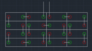
I am just wondering if most people avoid my configuration because it is one of the most likely to cause a huge short.

1612642059748.png
 
I like the idea of insulating the other battery terminals .... take the surgeon approach .... especially in the case of the bar type torque wrench ... anything added to the wrench is either going to risk making it inaccurate or make it more cumbersome and then maybe increase the chance of a fumble.
In the case where there is a lot of metal around the outside of the battery, just make sure there is nothing that will give it a voltage reference to the battery.
 
Yes.... but is that like saying 'it is only a small nuclear explosion'? These cells can dump a *lot* of current. Shorting just one cell will create a significant 'event'
Someone else suggested putting a hole in cardboard and covering the cells with that. I think that would be cheap and effective. Yes, I like cheap and effective... :ROFLMAO:
 
You could make a small nuclear explosion with busbars if you try hard enough. Especially if you rush and try to hold more than one at a time.
 
My JB Welded binding posts take 80 inch-lbs (max of my new wrench) with no issue at all, so a JB-welded grubscrew is only coming out if you sheer the entire column of stainless steel with JB Weld and aluminum threads attached out of the aluminum terminal.

For what it’s worth, I decided to hook up my 600 inch-lb torque wrench and see how much the JB weld could take. Somewhere between 80 and 100 inch pounds, the screw started unthreading. No JB Weld stuck in the male threads and the female threads look perfect.

I did not clean this bolt with Acetone before glueing it, so it probably came free earlier than it would have if we’ll-cleaned first.

But staying well-attached up past 80 inch pounds means the Allen Head Wrench can probably be skipped when grubscrews have been glued in with JB Weld...

And remember, the Aluminum terminals are only rated for 8Nm / 70 inch-lbs of torque, so I think the overall message is that JB Weld will allow you to ‘export’ the torque rating of the stud to the grubscrew (probably Loctite Red as well, someone needs to perform a similar test using a binding post).
 
I think 100 inch lbs would tear the terminal off if the threads didn't give way.
That's awesome news that JB weld works so good. I'll have to use some to hold my helicoil back in. I ripped that out with 80 in lbs
 
I am just wondering if most people avoid my configuration because it is one of the most likely to cause a huge short.

View attachment 36197

My AGM bank (8s1p) ends similarly.
You don't have compression between first and last cell (although perhaps clamped in position by compression fixture), could insert an insulating sheet.
 
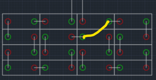
The short I had was across the terminals shown in yellow. That might not be the absolute worst case but it was quite a show.
That looks like 2 negatives but I don't think it works that way serial.

1612647228803.png
 
You shorted a 7S battery (22-24V depending on SOC).
That's why only that half of my cells showed signs like pitted terminals and seized nuts.
The negative terminal of the main positive cell got melted and blown off. The rest of the cells seem to have faired ok so far.

If I do that again I can probably get my studs out if I hurry while they're still hot.

Melted and blown off by the direct arc from wrench.

But the others in that series string which all briefly carried perhaps 20kA (probably less due to wrench resistance) had damage to electrical contact face? Could be poor contact, like that article I found which described many small points of contact. Copper on copper would withstand the abuse much better.

Think they were well torqued? Cleaned of native oxide? Corrosion inhibitor?

Since oxide starts to re-grow immediately in atmosphere, I wonder about scrubbing off old oxide, spread corrosion inhibitor, scrub to remove fresh oxide, wipe off inhibitor to remove particles, apply additional inhibitor and assemble.

(In my dream world I would remove oxide under vacuum or with inert atmosphere, then deposit tin plating.)
I don’t see how you get to 20kA.

IR per cell is 0.25 mOhm, plus probably that much again for each busbar and contact resistance times 2, so 7 x 0.5 mOhm for the full string is probably a reasonable swag (without adding a bit more for the wrench),

~23V / ~3.5 mOhm = ~6,571A - high enough to generate a great amount of heat and cause damage, for sure, but not 20,000A.
 
Melted and blown off by the direct arc from wrench.

But the others in that series string which all briefly carried perhaps 20kA (probably less due to wrench resistance) had damage to electrical contact face? Could be poor contact, like that article I found which described many small points of contact. Copper on copper would withstand the abuse much better.

Think they were well torqued? Cleaned of native oxide? Corrosion inhibitor?
I am wondering about contact issues as well. That is why I have been cleaning all of my terminals and busbars with scotchbrite and putting on noalax. I was just putting my battery configuration to serial at the time but I tightened the terminal nuts by hand so I don't know how what the torque was. I was just finishing up.
Since oxide starts to re-grow immediately in atmosphere, I wonder about scrubbing off old oxide, spread corrosion inhibitor, scrub to remove fresh oxide, wipe off inhibitor to remove particles, apply additional inhibitor and assemble.

(In my dream world I would remove oxide under vacuum or with inert atmosphere, then deposit tin plating.)
The pitting was only in small areas on a few terminals. I have cleaned the terminals a few times but I will do them all again. I started cleaning my busbars with scotchbrite too. They are tarnished.
 
I don’t see how you get to 20kA.

IR per cell is 0.25 mOhm, plus probably that much again for each busbar and contact resistance times 2, so 7 x 0.5 mOhm for the full string is probably a reasonable swag (without adding a bit more for the wrench),

~23V / ~3.5 mOhm = ~6,571A - high enough to generate a great amount of heat and cause damage, for sure, but not 20,000A.
 
Difficult to know what size that battery is. He said 400Ah, so it is at least 2P.

If we assume a 12V battery, each parallel pair of cells is 0.5 mOhm / 2 = 0.25 mOhm and 4 in series translates to ~1mOhm.

13.2V / 1 mOhm = 13,200A (about double the level I was estimating for Arther Eld’s 1P7S battery because of the lower effective IR from 2 cells in parallel).

If that was a 24V battery, resistance doubles but so does voltage, so current stays about the same (though Watts and heat generated doubles).
8AWG has a resistance of 0.628 mOhms per foot, so 15’ translates to 9.42 mOhms.

In total he had to have resistance of over 10 mOhms and no way he gets to the current levels he states.

His ‘measurement’ only shows that he exceeded 1000A and blew his 300A fuse.

With that 15’ 8AWG wire, he was almost certainly under 1300A if that was a 12V battery and under 2600A if that was a 24V battery...
 
I don’t see how you get to 20kA.

IR per cell is 0.25 mOhm, plus probably that much again for each busbar and contact resistance times 2, so 7 x 0.5 mOhm for the full string is probably a reasonable swag (without adding a bit more for the wrench),

~23V / ~3.5 mOhm = ~6,571A - high enough to generate a great amount of heat and cause damage, for sure, but not 20,000A.

Consider 3.4V cell with 0.17 milliohm resistance. (typical reported resistance vs. spec)
3.4/0.00017 = 20,000A
using your 0.25 milliohm figure,
3.4V/0.00025ohm = 13,600A

Correct, busbars and other resistance (cables, wrenches) add resistance and reduce the current.
In which case we get to your figure. Cross section of busbars will make a difference.

Glancing at wire resistance charts (for copper) and ampacity (copper and aluminum), I think a 3" long aluminum busbar would need to have cross section in the range of 8 awg to 10 awg in order to be 0.25 milliohm for 3 inches. Are they that skinny? I'd want more for 100 or 100's of amps.
Mine are about 2mm x 15mm meaning a cross-section of 30mm^2 corresponding to somewhere between 3AWG and 2AWG and resistance of ~0.18 mOhms/ft or ~0.04 mOhms over their 2.5” length.

The 2 contact resistances likely dominate the busbar resistance itself.

So far, when I’ve used the deltaV / deltaI method, I have measured total resistance through cell from busbar well in excess of these levels (probably because I was not torqued down heavily-enough).

What deltaV / deltaI measurements have others achieved with these EVE 280Ah cells?
 
Mine are about 2mm x 15mm meaning a cross-section of 30mm^2 corresponding to somewhere between 3AWG and 2AWG and resistance of ~0.18 mOhms/ft or ~0.04 mOhms over their 2.5” length.

The 2 contact resistances likely dominate the busbar resistance itself.

So far, when I’ve used the deltaV / deltaI method, I have measured total resistance through cell from busbar well in excess of these levels (probably because I was not torqued down heavily-enough).

So the simple resistivity calculation suggests massive current, but IR drop measurement says a fraction as much.

Contact resistance probably dominates. Not a good thing, because that's where all the energy is deposited. Potentially, one of them goes into runwaway faster than the fuse can blow. Balance of system is supposed to hold together long enough for OCP to clear a fault but these busbars are an unknown quantity and subject to varying assembly techniques.

A UL listed battery would be tested for that. We're crowd-sourcing the test! :)
 
Back
Top