diy solar

diy solar

MUST PV1800 5kW VHM Charging algorithm for Lithium battery

chladekj

New Member
Joined
Nov 3, 2021
Messages
29
Location
Czech Republic
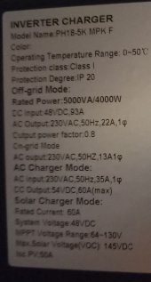
What is better for my LiFePO4 and MUST PV1800 5kW VHM inverter?

Setting:
  • Battery type Lithium (par. 14 = Li)
  • Bulk charging voltage 55,2V (par. 17)
  • Float charging voltage 54,4V (par. 18)
With these settings, the charge voltage does not exceed 54,0V even if there is a lot of unused energy from the sun. Only at the end of charging it goes above 54,0V. So the charging takes a too long time.
  • Question: from where the 54,0V goes? I did not find any parameter with this value
If I change the setting of battery type to User (par. 14 = USE), then the voltage rise above 54,0V

Does anyone know how the Charging algorithm for Lithium battery works at this inverter?
Or what is the difference between the charging algorithm for Lithium and lead acid?
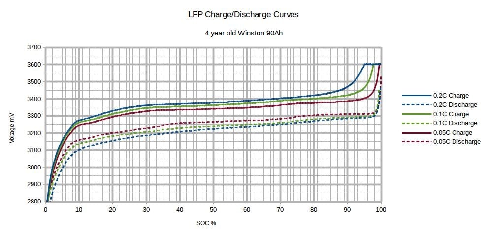
  • In the handbook, there is only a graph without any explanation
Thanks for your opinion and discussion.

1682407523673.png1682407855352.png
 
From the graphs, it seems that for lead-acid,it does mainly constant voltage (CV) and the current tapers down naturally. For LI, it does proper constant current (CC) up to the float voltage. As current decreases naturally at that point, it seems the algorithm increases the voltage up to max voltage (bulk?) and then continue with CV at this higher voltage.
What is unclear is how the algorithm decides to go to this higher voltage: is it current based or time based ?

That might explain why it takes a while for the battery to be fully recharged, especially if it's time based.

To tell you the truth, I haven't seen such a graph being used for Lithium chargers. Usually the algorithm is fairly simple: CC up to max voltage, then switch to CV up to a certain current threshold, the. stop charging.

I have a MUST 3K 24v, but it's in the process of being installed, so I can't say if that's actually how it behaves. But your findings are interesting.

In general, most users prefer to go with the USE setting anyways, so that they have control over the charge voltages.
Not sure if that setting behaves the same as the graph for Lithium (LI) or not.

It's funny that I have never looked at those graphs in the manual. Just thought they were standard...
 
Set the parameters in the USER options (assuming you have a 16s LiFePO4).
  • Bulk charging voltage 56V (3.5V per cell: you could go up to 3.65V per cell, but not needed)
  • Float charging voltage 54V (3.375V per cell; be below 3.4V per cell)
Disable all the other things that are lead acid specific.

With these settings, the charge voltage does not exceed 54,0V even if there is a lot of unused energy from the sun. Only at the end of charging it goes above 54,0V. So the charging takes a too long time.
  • Question: from where the 54,0V goes? I did not find any parameter with this value

The voltage will be pulled down to battery voltage. The 54V you see is the battery voltage. Once the battery charges up, this voltage will go up. This is because of the flat voltage curve of LiFePO4:

qidwvcdb3z4i.jpg
 
Thanks for the answers, I will set the USER battery type. According to me, the bulk 3,5V is too high and 3,45 is enough. But the discussion about the best charge voltage levels is for another thread.

But still thinking about the meaning of the LI algorithm. I would suppose that the first voltage level corresponds to par. 18 which I set to 54,4V and the second level to par. 17. which is 55,2V. But in reality, the first voltage level is only 54,0V. I draw the green line into the graph how it behaves. I will try to ask MUST support for a better explanation, maybe different parameters are assigned.

1682431519279.png
 
. But in reality, the first voltage level is only 54,0V

Did you measure this when the charger is connected to the battery and charging? In that case, this would be correct. As I said, the voltage drops to the battery voltage (constant current) before it gets to the higher state of charge (constant voltage).

For example, if you were to take a single cell at 3.4V, and take a power supply set to 3.6V before connecting. Once you connect, the voltage at the supply will drop to 3.4V and provide as much current as it can. Over time, the battery voltage will rise until it reaches 3.6V with the current tapering off as it goes.
 
Seems that I find the cause, there is ca 0,4V difference between adjusted and regulated voltage
So if I adjusted 54,4V - the real voltage was regulated to 54,0V
And if I adjust 54,8V I got 54,4V which I need. And also if I adjust i.e. 56,5V, I got 56,0V. Always 0,4V difference
 
I know there is a calibration register in the protocol for this, but it surprises me it wouldn't have been calibrated at factory. Make sure your multi meter is correct - you probably want to test it with a voltage reference or something to make sure the read out is correct. Just in case...
 
Seems that I find the cause, there is ca 0,4V difference between adjusted and regulated voltage
So if I adjusted 54,4V - the real voltage was regulated to 54,0V
And if I adjust 54,8V I got 54,4V which I need. And also if I adjust i.e. 56,5V, I got 56,0V. Always 0,4V difference
got the same difference... checked with bms and voltmeter (YR1035+)
have older inverter version... PH1800-MPK-PLUS
so got good charging with
[07]=52.4 - did not tested (testing UPS mode now), will test on next discharge-charge cycle in FL mode
[08]=53.8
[09]=54.2
[45]=[08]+0.2=54.0
[46]=[10]+0.2=54.4
+ set discharge and overcharge related parameters
[10]=44.0
[11]=48.0
[12]=59.0
[50]=59.0
 

Attachments

  • 20230423_230700_20230423_231042525.jpg
    20230423_230700_20230423_231042525.jpg
    60.8 KB · Views: 4
Last edited:
I know there is a calibration register in the protocol for this, but it surprises me it wouldn't have been calibrated at factory. Make sure your multi meter is correct - you probably want to test it with a voltage reference or something to make sure the read out is correct. Just in case...
Voltage checked with DALY BMS and two multimeters BENNING. The displayed voltage is correct, only the setting values are shifted plus 0,4V
 
Voltage checked with DALY BMS and two multimeters BENNING. The displayed voltage is correct, only the setting values are shifted plus 0,4V
Do you see any difference when charging form Solar and from Utility? I have different shift for Solar (0,2V) and Utility (0,8V) charge on Must 5.5kW
 
Back
Top