diy solar

diy solar

Newbie help! Parallel BMS wiring -- with terrible MSPAINT drawing!!

cyberfed

New Member
Joined
Mar 23, 2024
Messages
42
Location
Florida
Hello bright minds,

First off I apologize for my terrible drawing, its a gift I was never blessed with but it gets the point across. I have 3 batteries that are already in a 13S configuration (they came from Audi Q5 hybrid vehicles) they are in a nice metal enclosure and you just have your two terminals. I bought 3 JK BMS's and I want to use this setup in a parallel configuration for charging/discharging. I bought 3 two-pole DC breakers rated for the max amps of the BMS which will sit in between the BMS's main negative out from the battery (P-) to a busbar rated again for way more amperage than necessary. The same goes for positive, I run a cable from the positive terminal of each battery through the breaker and then to the busbar. From there the busbars are my "true neg/pos" for connecting say an inverter or charger.

I didn't include the balance wires that go to each battery, the diagram is bad enough, but each battery has the appropriate balance wires run to it and tested (individualy/per battery) there's no sharing of the balance wires across any BMS just with the battery its aligned with.

Is this the way to go? Do I need fuses? Is there a better design? I want to be safe. I've never paralleled BMSs before. This sounds right in my head but I dont want to find out I was wrong the hard way!! The 13S packs are Li-ion batterys (NMC). Any and all advice is appreciated.

Cheers!
 

Attachments

  • parallel.png
    parallel.png
    213.4 KB · Views: 24
We generally fuse the positive as a legacy of negative grounded systems, but almost everybody's running isolated battery buses now and I assume you are too, so it's necessarily wrong to break the negative if you prefer it that way so that it resides on the same line as the BMS.

Paralleled batteries are naturally balancing, so I don't fus with even wire lengths. If you're looking for reading tea leaves of like how do you put the inverter in between the batteries on the bus bar for perfectly even distribution, there's no perfect way to do it. But I don't think it matters. Even if they get slightly out of balance in the mid range voltages, they will still figure it out somewhere between there and fully charged or discharged. That's assuming your C rates are generally less than .2. At higher C rates there is more stress on parallel balancing.

As far as fuses and breakers, it's an open topic of discussion. Personally I prefer only Class T fuses and no breakers. I'm also a hypocrit though, my Lifepower4 is paralleled into my system with only it's 100A breaker and no fuse. But when I'm building packs, it's Class T only.

If you use breakers, select and research them carefully. Be sure they're nonpolar or understand the implications of using polar breakers.
 
Thank you @hwy17! I'm a bit confused at what you are saying. Forgive me but I'm completely new at paralleling BMSs with individual packs. Are you saying I should add either a fuse/breaker on the negative only between the P- of the BMS to the busbar? Each BMS has active balancing built into it so it'll balance the respective pack on its own. I'm not using the bus bar necessary to ensure "perfect balance" when charging / discharging.

This pack will NOT be pulling a lot of amp's ever. It's going to be used to power small things around the house. I got 2 pole Westinghouse breakers rated for 63VDC. I am not aware of polar/nonpolar breakers I will have to research that.

To reiterate from my drawing are you saying essentially ditch the 2 pole DC breakers and just put a breaker or a fuse on the negatives from P- BMS to the bus bar?

Sorry for the redundancy I just need to make sure I get this right for safety as well as knowing the dimensions of the box I am going to build for it.

I chose breakers (especially 2 pole) so I could completely "disconnect" one of the batteries if need be, not so much for over current safety reasons, but for say for some reason I need remove a battery for service of some kind. I saw a lot of videos and a lot of people were putting a disconnect switch only on the positive end but then again they don't show their entire setup.

I have a few ANL 60A fuses laying around, would those be a better idea, place them on pos or neg? I was just looking real quick at the class T fuses you mentioned I have to research those. I have seen them but don't know much about them. Hence I'm here checking with the smart folks such as yourself who have done this stuff safely.

I needed a little hand holding on the best way to go about this. If I need by parts/bits/ect.. that's no problem.

Thank you kindly for you help and advice!
Respectfully,
Cyberfed
I may have just been confused actually, and thought it was a picture of single pole breakers on negatives. And I meant that single pole breakers usually go on positives.

If they're double pole breakers you can ignore me and go ahead.
 
To reiterate from my drawing are you saying essentially ditch the 2 pole DC breakers and just put a breaker or a fuse on the negatives from P- BMS to the bus bar?
You shouldn’t need both fuses and breakers. But you should be sure that you have real confidence in the quality of those breakers, and that they’re non-polarized. On the forum you tend to see more class T fuses than breakers because the fuses are much cheaper than high quality breakers.
I have a few ANL 60A fuses laying around,
I don’t think I would count on these to safely blow if there’s a short in the system.

Hence I'm here checking with the smart folks such as yourself who have done this stuff safely.
If you really want the utmost in safety, either ditch the Li-ion for LFP, or make sure they’re stored far away from any inhabited structure. LFP is inherently safer.
 
Awesome thank you for the additional info!

@LakeHouse - I agree with almost all of my builds are LFP, but these fell into my lap and I'm not going to waste them. They are properly stored, and evaluated during their life with high end equipment.

Sorry about the drawing - yes they are double pole breakers. I have to check about the polarized situation. I don't know what kind they are, I guess I'm used to putting fuses for example on the negative (black) cables since that is the true path of electron flow. The whole non-polarized thing makes sense after reading up on it. I'm honestly probably going to go with the T-fuse I feel its safer than a breaker.
 
@hwy17 So I was looking at T-fuses last night. My goodness they are expensive along with the holders for them. Am I looking in the wrong place? I thought this was supposed to be cheaper alternative to breakers. Right now in my cart on Grainger.com I have 6x 60A Littlefuse Type T fast acting fuses (3 spares) each is like $30 bucks and then a fuse holder that holds 3 fuses that is $25 bucks.

Do those prices sound right? Anyone got a link to a good fuse + holder that is quality and not expensive? I looked on amazon but they mosty had 100A and higher fuses and fuse boxes.

Oh I checked my breakers, they say on the side "Line/Load protected" does that mean non-polarized? From what I could find on the web it does, but maybe someone here has more expirenece see pics of the breakers attached. I emailed westinghouse as well awating a formal response, I got the standarded canned response saying its being routed to the right team..blah blah...

What do you all think of these breakers? Will they do the job, would you have confidence in them (please be honest). I dont mind saving them for another project if T-fuses are the way to go. Thanks gents!!!
 

Attachments

  • 1.jpg
    1.jpg
    228.3 KB · Views: 5
  • 3.jpg
    3.jpg
    209.2 KB · Views: 5
  • 2.jpg
    2.jpg
    155.3 KB · Views: 5
I had to look those up 😁;


IMG_1590.jpeg


There is a Forum Member who lost his house ( fortunately his family all got out alive ), so there is a bit of a sobering moment currently or perspective towards the “Class T Fuses”.

Even with my minimal systems, I am looking at my existing setups with a critical eye & will probably making some alterations.

Normalcy Bias can sometimes have ourselves 2nd guess or risk levels ,,, what does that mean 🤷‍♂️ ? ,,, well if I have never blown a fuse or had a fire that is my normal ,,, until it isn’t.


Fail Safe & Simple & Safer might be the path to take. We all have to decide when designing our systems. For me where required, that is pointing to Class T where it is needed / desired.


Thread 'House burned down'
https://diysolarforum.com/threads/house-burned-down.83098/


Another fuse thread for ya;

Post in thread 'Class T vs ANL fuse'
https://diysolarforum.com/threads/class-t-vs-anl-fuse.13913/post-155368


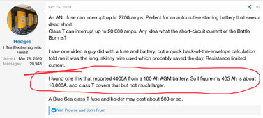
But All I Have is 1 - 100Ah AGM;

IMG_1591.jpeg


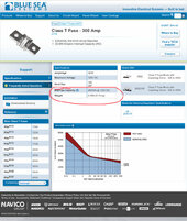
Class T;

IMG_1593.jpeg


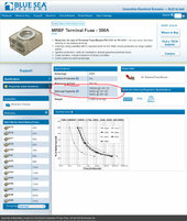
MRBF ( Used with battery fuse blocks );

IMG_1592.jpeg
 
Last edited:
@RV8R
Ok, yep you've scared me sober now. I had used ANL fuses coming out of the packs going to the inverters (most packs right now I have are 16S LFP no parallel). Renogy and Victron is what I based my design, they recommended ANL fuses. But it seems that's not a good idea.

So time to spend a fortune on fuses..

Here is the plan tell me if this is the way to go:
16S packs with 74AH batteries @48v for around 3.7kwH --->coming out of the pack Class T 5119 fuse in the 1st picture to the inverter or solar charger.

For the parallel pack (13S3P - between each battery and the terminal block (which needs to be mega beefy) Class T fuse (again 1st picture is what I'm using for all) and then again another fuse coming out of the main pos/neg that go to an inverter.

Anywhere else needed? I bit confused on the 300A rating. So this isn't for preventing going over the 60A limit of the BMS, its more for a short situation where huge amounts of currents (easily breaking 300A) happen and the fuses would blow and are made to handle that level of short without arcing or somehow continuing the short to happen? Is that the theory?

Guys seriously, that post scared the crap outta me, really need some help here if I'm missing a place for a fuse please let me know. The 16S 48V 74AH packs came with a custom metal enclosure (LFP) and it has a cheap DC breaker built in on it for 125A. As that PCB board is rated for 100A as is the BMS.

So 300A T-fuse coming out of said metal enclosure needs to be on the positives (red) that lead to inverters or solar chargers depending on what we are doing charging vs discharing.

Also I am building a few 24V 8S packs using JKBMS's not paralleled. No custom enclosure. LFP. Same deal put a 300 Class T on the main + out that will connect to the inverter or solar charger.

Thanks guys I really need some help here, I have ANL fuses all over the place and now I'm scared, granted everything is LFP. But still. Since these things are expensive (which I dont love but I can afford it, I make good money and safety is #1) I just need to know where they need to go on the paralleled system we this topic is about as well as just a regular pack 8S 24V 74AH. That way I know how many fuses and fuse cases I need to buy.

THANK YOU guys. Seriously, I'm super annoyed I was told to get ANL fuses. I have so many. I was also buying them for the current limit of the BMS not 300V. Sigh. This is why I'm here asking the experts how they would do it.
 
I bit confused on the 300A rating. So this isn't for preventing going over the 60A limit of the BMS, its more for a short situation where huge amounts of currents (easily breaking 300A) happen and the fuses would blow and are made to handle that level of short without arcing or somehow continuing the short to happen? Is that the theory?
I don't think it was necessarily a recommendation for a 300A rating. But what you're suggesting (a high-ish rated Class T to protect specifically against a dead short) isn't unreasonable, as long as you also have another method of protecting against the non-short overload case. So breakers rated to protect your wiring, and a class T for each battery-busbar circuit.
So 300A T-fuse coming out of said metal enclosure needs to be on the positives (red) that lead to inverters or solar chargers depending on what we are doing charging vs discharing.
Fusing the positive is typical, but not the only way to do it.
The way you have it drawn up, I would install Class T's on the positive of each battery, as close as practical to the battery itself. You can also do a Class T to the inverter, but it's arguably less of a necessity since the inverter isn't capable of producing the nearly unlimited current that the batteries are capable of. It must have a fuse or breaker, but not necessarily Class T. In my system, I have only one battery, so only a single Class T, and my bus bar-to-inverter circuit is protected by an ANL at the bus bar and an MCCB, but that's more for ease of isolation than anything else.
Assuming your Charge Controller is separate from your Inverter (i.e., not an All-in-One), you definitely don't need a Class T for that circuit. Again, it does need a fuse or breaker, but Class T would be overkill. Personally, I use an ANL fuse for my circuit between the bus bars and the SCC.
The theory being that a dead short anywhere in my DC system needs to be protected from the battery current with a Class T. Once the Battery Class T blows, nothing else can possible provide more than 10's of Amps, so ANL's will do just fine.
 
@RV8R
Ok, yep you've scared me sober now. I had used ANL fuses coming out of the packs going to the inverters (most packs right now I have are 16S LFP no parallel). Renogy and Victron is what I based my design, they recommended ANL fuses. But it seems that's not a good idea.

So time to spend a fortune on fuses..

Here is the plan tell me if this is the way to go:
16S packs with 74AH batteries @48v for around 3.7kwH --->coming out of the pack Class T 5119 fuse in the 1st picture to the inverter or solar charger.

For the parallel pack (13S3P - between each battery and the terminal block (which needs to be mega beefy) Class T fuse (again 1st picture is what I'm using for all) and then again another fuse coming out of the main pos/neg that go to an inverter.

Anywhere else needed? I bit confused on the 300A rating. So this isn't for preventing going over the 60A limit of the BMS, its more for a short situation where huge amounts of currents (easily breaking 300A) happen and the fuses would blow and are made to handle that level of short without arcing or somehow continuing the short to happen? Is that the theory?

Guys seriously, that post scared the crap outta me, really need some help here if I'm missing a place for a fuse please let me know. The 16S 48V 74AH packs came with a custom metal enclosure (LFP) and it has a cheap DC breaker built in on it for 125A. As that PCB board is rated for 100A as is the BMS.

So 300A T-fuse coming out of said metal enclosure needs to be on the positives (red) that lead to inverters or solar chargers depending on what we are doing charging vs discharing.

Also I am building a few 24V 8S packs using JKBMS's not paralleled. No custom enclosure. LFP. Same deal put a 300 Class T on the main + out that will connect to the inverter or solar charger.

Thanks guys I really need some help here, I have ANL fuses all over the place and now I'm scared, granted everything is LFP. But still. Since these things are expensive (which I dont love but I can afford it, I make good money and safety is #1) I just need to know where they need to go on the paralleled system we this topic is about as well as just a regular pack 8S 24V 74AH. That way I know how many fuses and fuse cases I need to buy.

THANK YOU guys. Seriously, I'm super annoyed I was told to get ANL fuses. I have so many. I was also buying them for the current limit of the BMS not 300V. Sigh. This is why I'm here asking the experts how they would do it.

Hi @cyberfed

Honestly, not trying to “scare” you at all ,,, just offer some awareness on fuse / breaker options. I do believe the Forum Member’s report on his DIY system burning down his home has shown us all to ponder our designs somewhat. The fuse in that case is speculation, & other things have to go wrong also ,,, these things much like aviation disasters are typically a series of things that align to cause an unfortunate issue.

So DIYers, & Members on This Forum try to “have each other’s 6 (back)”. Not fear tactics, but open dialogue & reasoning ,,, it is how I have learned something. Even the most careful, can have a brain fart & make a mistake ,,, Any One of Us.

So in your case ,,, post, ponder, learn, review, & ask questions ,,, it is the magic of these forums.

I am far from any expert on any of this, & in my mind the systems “of the whole” & how it is protected is what makes it safe. What does that mean 🤷‍♂️ ? ,,, I asked about a disconnect for my 60vdc array & am still paralyzed. Turns out the breaker I was thinking of using, would probably cause a worse system than what I was trying to protect against 🤪;


Thread 'PV Disconnect for 600W Array ( 60 V @ 10 A )'
https://diysolarforum.com/threads/pv-disconnect-for-600w-array-60-v-10-a.81004/


300a rating ,,, if that refers to my post ,,, I was just digging up spec sheets for these types of fuses ,,, not recommending any amperage ,,, the IA seemed to be roughly the same for the same class. As @LakeHouse wrote the Class T would be good to have as close to the battery positive terminal as practical & unlikely other than the battery needed ,,, depends upon schematics / design, etc. What can produce the energy that an ANL can’t interrupt 🤷‍♂️? I am assuming just the batteries.
 
Last edited:
No I appreciate it @RV8R, I don't you had no ill intent, actually the opposite! I will be honest I didn't read the 30+ pages of the forum thread to read the whole story. Anyone have a 30 second version? I'm trying to understand how a short circuit (and where) would cause the ANL fuse (speculation sounds like) to break, and then arc continiously.

I mean the BMS has CC protection to kill the batteries upon a CC. The solar charge controller as well, mix in some fuses (ANL) along with inverters that are also fused and CC protected I'm left thinking, how did this happen? What was like you said the combination of events that lead to this?

I mean I sure as heck don't want to burn my house down! (I rent eeek!) so I REALLY APPRECIATE EVERYONE'S FEEDBACK! I'm not offended in anyway. I ordered a ton of those Class T fuses and fuse holders from Blue Sea last night. Some will have to be 'shared' when a pack is not in use (as I build so many portable house packs) to save some money. Because if I need to buy a Class T fuse between the battery and the inverter + every parallel connection (though I think I'm just going to keep those 3x 13S seperate now, I'm worred I don't know what I'm doing...) + one between the charge controller and the battery well that adds up to over a dozen class T fuses for me and I still have some more packs to build!! So yeah that hurt my wallet last night.

I am going to add a disconnect switch to all packs as well. Similar to how you have one on your solar panels right before going into the charge controller, though I guess some people use a breaker as a disconnect.

Westinghouse got back to me on the 60A double pole breakers. They said they are non polarized and can be used exactly as I described it, charging/discharging. To save a few bucks can I use those as disconnects (in combination with class T fuses)? Or would I be introducing a danger point with the breaker should whatever this CC scenario happens?

Yesterday I was really down on myself, I have been researching, reading books, solar company websites manuals ect... I thought I had good safety in place. I felt like giving up yesterday on all my projects because I felt like a total failure, puttting myself, property and family in danger. I'm feeling better today (I struggle w/PTSD/anxiety) and the reality is I wouldn't just give up, I've invested too much time and money to give up something I really do enjoy doing. It was a set back that's how I see it, learn from it, improve the systems, and life is good. Also unlike most people here, not that this somehow stops tragedy from striking but my packs can hold a lot of juice but I draw almost nothing from them. Right now my biggest usage is 53 watts of 120V for some grow LED grow light strips for my g/f's plants and flowers. We power our bedroom from a 3 lightbulb tall lamp that uses LED bulbs, that pulls 26 watts at 120v. So my amperage pull is so low that it sometimes doesn't even register on the Victron bluetooth app.

My solar charging is 6A tops @48v or 12A @24v (paralleled) or if I wanted 2x 6A @ 24V charging two packs (total of 4 panels I own as I'm sure you figured it out by now.)

I have a whole different question about LFP, SOC 3.2V - 3.6V how to know when stuffs full. But I'll research that first and then start a seperate thread if need be for that. I just finished up another 16S LFP 48V pack and I am starting the build of another identical one right now. Then after that is done I have 2x 8S 24V packs to build (I told ya a got packs all over the place!).

So any suggestions on how to improve my designs please let me know. My normal setup in the house is battery pack + inverter. That's it (well with a fuse of course). Since they are "mobile" packs they don't remain connected to the solar charge controller 24x7. Only when they need a charge.

I was surprised its a very cloudy day today and I am getting the full ~5.9A out of my panels to charge up a 24V pack that got depleted yesterday (using only 2 panels, didn't parallel them I should have but its hot out.)

Cheers mates, keep the good info coming!
 
Well I took the time to read the entire forum post of that poor guy who's house burnt down. Lots of speculation and a lot of it was just the same information repeated by different people in a slightly different manner. But I suppose that's how forums go. I was nice to see people being kind and not criticizing the guy. I really like the attitude in these forums.

There were some takeaways that I'm going to make some modifications to my packs. I'm fortunate that all my 16S LFP 48V packs are in metal enclosures (sold as part of a DIY kit). I do plan to add the t-fuses I ordered. I would like to put them before the BMS but there is simply no room for that. So they will have to be on the outputs of the boxes terminals (which are controlled by a breaker to turn them on/off that has me worried about the breaker in a on state causing the same type of issue. I'm going to look at replacements for it that fit the box with a higher AIC.

I have compression plates, but I did not use anything in between the batteries. I have since ordered FR-4 sheets that I can cut to the exact size of the battery and add that to them to protect from what appears could have been the whole inception of the fire. I have also ordered more (I have used this stuff in other pack builds after testing with a blow torch and my thermal imaging device) fiberglass insulation material that is fire resistant to 2500F. I stuff it around the pack as a filler if you will. I'm going to add some to my metal box enclosures where there are some voids, and around the BMS and breaker (big time).

I'm thinking of drilling a hole on the top to mount a fan to suck out exhaust. Not sure on that yet. I have a dog and hair is always everywhere. I'm afraid the pack will slowly start sucking in dog hair through the small holes in the case. I also had purchased a spray chemical that you put on wood to stop it from burning up to 2500F or so. I'm going to see if I can use it on metal or not. The metal box is thin and would easily melt in a thermal runaway situation. I'm also looking at placing firebricks on the top/bottom/sides of the boxes for added shielding. Along with a surface for the box that can handle the weight and wont burn, probably a thick piece of steel..thats going to cost me I dont have tools or materials to work with metal except some saws that can handle very thin metal.

I don't have parallel packs, the 3x Audi batteries that are in 13S configurations from the factory I decided to use them as single packs instead of paralleling them. Seems like that was a major culprit again possibly, in the fire. So I'm going to play it safe and not parallel them.

I do have 4x Renogy batteries brand new I bought new, 24V 25AH, that I will parallel and now I'm scared of messing up the process, the batteries have their own internal BMS. So I don't know if I could even add my own. When the time comes to build that pack I will of course reach out for help. I know I need a beefy bus bar, fused connections from each parallel battery to the busbar and again afterwards. According to Renogy's website the batteries internal BMS is configured for all the protections you would expect CC/UV UC/ OV OC ect.. after the T-fuses I would like to add a BMS to each battery but how would that even work? Putting a BMS on a single battery 4 times? its essentially a 1S4P configuration. They state they do not allow series connection of the batteries. They are also supposed to "self balance" each other with their internal BMSs. Basically it seems like Renogy is making it sound attach a pos/neg cable a breaker or fuse and then your load. Done. That makes me uncomfortable. They are not "smart batteries" so I cannot monitor each one, even if its connected to the solar charge controller made by the same company. I have a 500V external shunt they sell, I suppose that will give me insight to the entire pack if connected at the very end say after the bus bars?

I dunno thats a conversation for later. I still have a lot of contruction work to do as well as added additional safety to the packs I already have mentioned above so I have a lot on my plate.
 
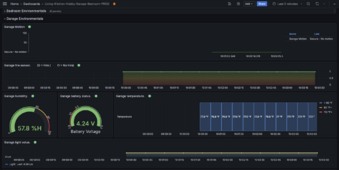
monitor.png
I would like to do something like this for the packs, with the appropriate sensors of course, mainly temp, fire, and voltage, the voltage you see here is of the small battery attached to the micro controller that is used as a "UPS" if power is lost via USB. It cannot handle reading high voltages. I purchased a separate sensor that can read voltages up to 60V and current as well. I need to learn how to use it, sparse documentation and how to wire it. If I can do that I could put one in each pack and build a dashboard like this to monitor real time as well as auto alerts if any value is out of tolerance (text message, email, audible alert anything really). This is all data fed from the microcontroller (ESP32-S3) to a Raspberry Pi I use as a server for this incoming data, I used a program to visualize the data. As you can see I monitor almost my entire house with various senors and alert methods. I saw something about IoTwatt or something like that in the other forum post of the burnt house... I looked into that and that project is dead and wouldn't work for what I want to do. Hey maybe a new business idea! I mean the guy was doing basically what I want (even using the same visualization software) but also providing way more metrics. Not sure how much I would be able to report on. We'll see. This is at the bottom of tinkering projects I have and its a long list!
 
Last edited:
Back
Top