diy solar

diy solar

One of 3 legs from the solar panels to the DC Disconnect has no voltage

Took a few more measurements and now i'm confused

Sorry, I didn't pay attention the first time but the voltage at leg 1 and 2 is -360V I confirmed the negative voltage on the working inverters disconnect as well. I also confirmed it wasn't the meter reading wrong by checking it against a power supply I have. So maybe they wired it in backwards? Or maybe it's supposed to have a negative voltage?

The readout on the working inverter shows this.

PV input 352V
Total output -19431 kW-Hr

I think I also forgot to measure the voltage at the fuse with the disconnect powered on last time.

Here are the probe results
with fuse 3 and 4 removed and disconnect switched off I'm getting -360 at both ends of the 1 and 2 fuses. With it switched on I'm getting -11v across N and H also at the fuses 1 and 2

with fuses 1,3,4 removed and disconnect on, I am seeing the same as above -11v everywhere after the fuse and -11v at the input of fuse 2
with fuses 2,3,4 removed and disconnect on, I am seeing the same as above -11v everywhere after the fuse and -11v at the input of fuse 1

I am attaching a picture of the disconnect if it helps
 

Attachments

  • 404063639_730744815599445_3253393934292503861_n.jpg
    404063639_730744815599445_3253393934292503861_n.jpg
    629.4 KB · Views: 11
Sorry, I didn't pay attention the first time but the voltage at leg 1 and 2 is -360V I confirmed the negative voltage on the working inverters disconnect as well. I also confirmed it wasn't the meter reading wrong by checking it against a power supply I have. So maybe they wired it in backwards? Or maybe it's supposed to have a negative voltage?
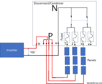
As you can see they put red tape on the 3 wires indicating those are the PLUS leads, connected to the "PV NEUTRAL INPUT" block from the schematic you posted before.
Just reverse the red/black in the diagram between inverter & disconnect/combiner of @FilterGuy
They fused & switched the negative wires.
Not usual , but the ideas behind is still the same.

Here are the probe results
with fuse 3 and 4 removed and disconnect switched off I'm getting -360 at both ends of the 1 and 2 fuses. With it switched on I'm getting -11v across N and H also at the fuses 1 and 2
My bet is on a bad inverter.
Pulling all the power to almost 0 volt.
Do you happen to have a clamp on amp meter by any chance ?
 
As you can see they put red tape on the 3 wires indicating those are the PLUS leads, connected to the "PV NEUTRAL INPUT" block from the schematic you posted before.
Just reverse the red/black in the diagram between inverter & disconnect/combiner of @FilterGuy
They fused & switched the negative wires.
Not usual , but the ideas behind is still the same.


My bet is on a bad inverter.
Pulling all the power to almost 0 volt.
Do you happen to have a clamp on amp meter by any chance ?
yes I have one. What should I test?

Also, not sure if it matters but AC was disconnected from the inverter while I was performing the tests.
 
yes I have one. What should I test?

Also, not sure if it matters but AC was disconnected from the inverter while I was performing the tests.
how much current is running through the 2 wires that do show voltage with the disconnect open, after you close the disconnect (switch it to on).

The 3rd string not showing any voltage is complete different issue, you probably have had only 2/3 of the PV power for a while.
Currently I would be mainly interested to see why the inverter complaints about low input.
 
As you can see they put red tape on the 3 wires indicating those are the PLUS leads, connected to the "PV NEUTRAL INPUT" block from the schematic you posted before.
Good Catch.

In some cases, they ground the positive side of a DC circuit. This was more common for PV circuits in the past when most of the SCCs were fully isolated from the AC. The other interesting point is that in the NEC, white is reserved for the grounded conductor (Neutral). I would not be at all surprised if the voltage between earth-ground and the 'neutral' was near zero on that circuit.
 
how much current is running through the 2 wires that do show voltage with the disconnect open, after you close the disconnect (switch it to on).

The 3rd string not showing any voltage is complete different issue, you probably have had only 2/3 of the PV power for a while.
Currently I would be mainly interested to see why the inverter complaints about low input.
I just checked all the white wires with red tape and they are at .02 Amps with the disconnect switched on All of the fuses were installed as well and inverter was powered off
 
I just checked all the white wires with red tape and they are at .02 Amps with the disconnect switched on All of the fuses were installed as well and inverter was powered off
To make a better assessment:
1) there must be light shining on the PV panels, preferable a lot , let's say around noon.
2) inverter in the off position.
3) you must be seeing the 350 volt between the common and both the 2 strings with the disconnect switch open (off position)
1700965185073.png
Disclaimer: no graphical artist genes in my family, sorry for the bad altered version.

4) then you close the switch, verify the voltage now dropped down to 11 volt. (this is not normal in a working condition, but since you measured it before, i would like you to verify this)
Measure between P & N (Positive) and Negative aka the input to the inverter.

Extra information that might be interesting: when you switch it off again, open 1 fuse holder and switch it on again and see what voltage you are now reading between the common and the joined parts (P & N)
switch off again, close the open fuse holder, open the other fuse holder, switch on again and measure the voltage one more time.
switch off disconnect & close the second fuse holder

5) Switch on disconnect & measure the current flowing through the 2 white wires with red tape.
You haven't mentioned what panels you have so we have to make guess, but normally in a working condition, you should see multiple amps flowing through the wires. let's say in the 2-10+ amp range.

Scenario 1:
If the inverter has a defect and basically is a short circuit on the input side, you would see 11 volt and multiple amps flowing.

Scenario 2:
Inverter sees the voltage and wants to startup but for some reason there is a high resistance in the PV string, that would drop the voltage at the input to 11 volt but the current would be in the range you measured before : way below 1 amp: 1/10 or 1/100 of an amp.

That info is essential to draw a conclusion imo.
 
To make a better assessment:
1) there must be light shining on the PV panels, preferable a lot , let's say around noon.
2) inverter in the off position.
3) you must be seeing the 350 volt between the common and both the 2 strings with the disconnect switch open (off position)
View attachment 180005
Disclaimer: no graphical artist genes in my family, sorry for the bad altered version.

4) then you close the switch, verify the voltage now dropped down to 11 volt. (this is not normal in a working condition, but since you measured it before, i would like you to verify this)
Measure between P & N (Positive) and Negative aka the input to the inverter.

Extra information that might be interesting: when you switch it off again, open 1 fuse holder and switch it on again and see what voltage you are now reading between the common and the joined parts (P & N)
switch off again, close the open fuse holder, open the other fuse holder, switch on again and measure the voltage one more time.
switch off disconnect & close the second fuse holder

5) Switch on disconnect & measure the current flowing through the 2 white wires with red tape.
You haven't mentioned what panels you have so we have to make guess, but normally in a working condition, you should see multiple amps flowing through the wires. let's say in the 2-10+ amp range.

Scenario 1:
If the inverter has a defect and basically is a short circuit on the input side, you would see 11 volt and multiple amps flowing.

Scenario 2:
Inverter sees the voltage and wants to startup but for some reason there is a high resistance in the PV string, that would drop the voltage at the input to 11 volt but the current would be in the range you measured before : way below 1 amp: 1/10 or 1/100 of an amp.

That info is essential to draw a conclusion imo.
OK thanks, I'll check them tomorrow or Wednesday and report back

regarding the extra info, opening and testing one by one each fuse. I did this today and every time was the same. 11 volts but I'll do it again tomorrow.

Panels are sunpower SPR-220 Specs here: http://www.solardesigntool.com/comp...7/SPR-220-WHT-U/specification-data-sheet.html

Scenario 2: when you say the inverter wants to start up. I have the AC breaker off to it so it is assuming the grid is down and is completely off. Should I perform the tests with the AC breaker on? or it doesn't make a difference?
 
regarding the extra info, opening and testing one by one each fuse. I did this today and every time was the same. 11 volts but I'll do it again tomorrow.
okay. without additional info, no idea yet.
I have those panels as well and I love them. Still going strong.
Around noon, with no or little overcast, you should see 3-4 amps per string _if_ the input of the inverter is a short circuit.
Scenario 2: when you say the inverter wants to start up. I have the AC breaker off to it so it is assuming the grid is down and is completely off. Should I perform the tests with the AC breaker on? or it doesn't make a difference?
Normally an inverter is powered from the DC (PV) side , not from the grid.
But your inverter might be different.
Sunnyboy/Fronius I have are "dead" when dark and at the creek of dawn they wake up again.
I don't know enough about your inverter if that is also the case.
 
To make a better assessment:
1) there must be light shining on the PV panels, preferable a lot , let's say around noon.
2) inverter in the off position.
3) you must be seeing the 350 volt between the common and both the 2 strings with the disconnect switch open (off position)
View attachment 180005
Disclaimer: no graphical artist genes in my family, sorry for the bad altered version.

4) then you close the switch, verify the voltage now dropped down to 11 volt. (this is not normal in a working condition, but since you measured it before, i would like you to verify this)
Measure between P & N (Positive) and Negative aka the input to the inverter.

Extra information that might be interesting: when you switch it off again, open 1 fuse holder and switch it on again and see what voltage you are now reading between the common and the joined parts (P & N)
switch off again, close the open fuse holder, open the other fuse holder, switch on again and measure the voltage one more time.
switch off disconnect & close the second fuse holder

5) Switch on disconnect & measure the current flowing through the 2 white wires with red tape.
You haven't mentioned what panels you have so we have to make guess, but normally in a working condition, you should see multiple amps flowing through the wires. let's say in the 2-10+ amp range.

Scenario 1:
If the inverter has a defect and basically is a short circuit on the input side, you would see 11 volt and multiple amps flowing.

Scenario 2:
Inverter sees the voltage and wants to startup but for some reason there is a high resistance in the PV string, that would drop the voltage at the input to 11 volt but the current would be in the range you measured before : way below 1 amp: 1/10 or 1/100 of an amp.

That info is essential to draw a conclusion imo.
Measurements done,

350V on lines 1 and 2
With the disconnect turned on voltage dropped to 15v
There are 4 white wires
wire 1 (connected to P) drawing 4 Amps
wire 2 (connected to P) drawing 4 amps
wire 3 (connected to P) drawing 0 amps
wire 4 (connected to N left of P) drawing 8 amps

I powered on the inverter with the AC breaker and see the same numbers
 
Normally an inverter is powered from the DC (PV) side , not from the grid.
But your inverter might be different.
Sunnyboy/Fronius I have are "dead" when dark and at the creek of dawn they wake up again.
I don't know enough about your inverter if that is also the case.
the way I understand it is there is a safety switch built in to the inverters. When the grid goes down the inverter shuts off to prevent backfeed to the grid.

we also have a fronius in front and it does the same thing. If I flip the ac breaker off the inverter shuts down. At night the inverters are in a standby mode until DC is detected
 
Measurements done,

350V on lines 1 and 2
With the disconnect turned on voltage dropped to 15v
There are 4 white wires
wire 1 (connected to P) drawing 4 Amps
wire 2 (connected to P) drawing 4 amps
wire 3 (connected to P) drawing 0 amps
wire 4 (connected to N left of P) drawing 8 amps

I powered on the inverter with the AC breaker and see the same numbers
My diagnosis from this :
Your inverter has a short circuit on the input of the PV.
Your panels are in short circuit mode, the 11-15 volts you measure is voltage loss over the lines between combiner/disconnect and inverter under the short circuit load.

@FilterGuy do you agree with this ?
 
the way I understand it is there is a safety switch built in to the inverters. When the grid goes down the inverter shuts off to prevent backfeed to the grid.
That is the case with all grid tied inverters: part of UL1741

we also have a fronius in front and it does the same thing. If I flip the ac breaker off the inverter shuts down. At night the inverters are in a standby mode until DC is detected
My Fronius/SMA are completely dead, nothing on the LCD display when there is no light shining on the PV panels.
Even with the AC still connected. It draws maybe 25mA so maybe 6 watt from the grid.
 
@FilterGuy do you agree with this ?
It sure looks that way.

Try disconnecting the inverter from the junction box and see if the voltage goes back up on the junction box output.

As an aside: Someone might ask why the fuses aren't blowing if there is a short on the output. The answer is they are not designed to blow in this situation. The fuses are intended to blow if there is a short on the string and the other strings pump too much current into the short.

By selecting a wire that is sized to handle 1.55x the Array Isc, there can be a dead short on the combiner output and nothing will burn. The reason it is done this way is that the Isc and Imp are so close to the same that it is almost impossible to select a fuse size that would 1) do any good and 2) not blow during normal operations.
Thanks guys, Is it common to see this type of short on an inverter?

I'll disconnect the inputs from the inverter and cap them off and test again.
 
Thanks guys, Is it common to see this type of short on an inverter?

I'll disconnect the inputs from the inverter and cap them off and test again.
I don't know how common it is but I have heard of it before.

BTW: Visually inspect the wires and the connection at the inverter. There could be a short before or at the inverter that you could correct.

If you have a thermal camera... use it to look for hot spots in the wiring. If there is a short it is likely to be hotter than everywhere else.
 
thanks, will have to clear out some stuff that is in the way to get to the inverter, will report back in a few days
 
Back
Top