diy solar

diy solar

Option to bypass inverter - Transfer switch?

kolek

Inventor of the Electron
Joined
Sep 29, 2021
Messages
510
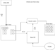
Need a switch to bypass the inverter. Maybe it's called a transfer switch?
Meaning, in cases where I need to work on the inverter and we want to keep the electric working in the house, want a way to be able to switch grid between the inverter and a direct connection to our electric panel.
We have 3 input wires coming from grid that give us 100V and 200V.

I think I need some kind of DPDT or 3PDT transfer switch for this? Not sure of the correct terminology.

Can anyone recommend something simple and reliable on Amazon that does this? It doesn't need to be automatic and it doesn't need to have an interlock.
 
the TS is center left
grid comes in from the top

critical loads panel is the big one to the right

1714283607358.png


schematic is in post #1 of MY BUILD THREAD, which as a link in my signature below
 
@dougbert
Thanks a lot for that tip, I'll check into that.
My goodness that setup is so professional and fireproof looking. That little setup there probably cost more than the whole house I'm living in.

And the amazing thing about the product you're recommending is according to Amazon it's unisex and a 4-stroke engine that runs on gasoline! lol
Item weight says 12 lbs. Would cost me a fortune to ship to Japan but it's an option.

Anyone have anything a little smaller?
 
Last edited:
Split the grid to go to inverter and panel.
Put disconnect between grid and inverter so you can turn off power to inverter.

Need a transfer or isolation switch on panel to select grid or inverter. That way you don't send grid power to the load output of the inverter.
 
I use this as a selection switch for the output (to loads):

Basically it's a 2 pole manual transfer switch, which allows only on input to be selected at a time.
One of the inputs is the grid, the other is the inverter's output. That way if I need to shutdown the inverter or if there is a fault, I can choose to power the loads directly from the grid.
Check around, maybe they have a 3 pole version.

On the AC IN to the inverter, I also have an AC breaker, so I can cut power to the inverter, for maintenance etc...
Wow that looks good. Just need a 3 pole version of that.
 
Is it also necessary to get another switch to enable the cutoff of the grid feeding back into the output of the Inverter? I assume yes. Otherwise when I switch to bypass the input to my inverter, that shuts of just the inverter input, but the inverter output is still connecting to my main electric panel.
 
Found this:
1PCS MTS Dual Power Manual Transfer Switch 1P 2P 3P 4P Mini Interlock Circuit Breaker AC 6A-125A 50/60HZ Dain Rail

Let's be honest. It's prolly a piece of junk, but I should rarely need to use it.
Great.
I use mine solely as a manual transfer switch. I do not count on it to be a breaker in case of overload. So I have proper breakers before and after.
You should get a model that will handle your max loads amperage though...
 
Is it also necessary to get another switch to enable the cutoff of the grid feeding back into the output of the Inverter? I assume yes. Otherwise when I switch to bypass the input to my inverter, that shuts of just the inverter input, but the inverter output is still connecting to my main electric panel.
I use the MTS on the OUTPUT (to loads panels).
I'm not understanding your intentions... Can you scribble a diagram of your setup?
 
I use the MTS on the OUTPUT (to loads panels).
I'm not understanding your intentions... Can you scribble a diagram of your setup?
I think it's easier to explain. When we switch to bypass the inverter, 2 things need to happen:
1. Switch grid input from inverter to loads panel
2. Turn OFF output from inverter to loads panel

Isn't that correct?
 
OK, so about #2 ‐ It depends what you want to do. If you are doing serious maintenance (like rewiring) then yes, you will want to turn off inverter output to the MTS. But in most cases the MTS is enough.
Most inverters have an ON/OFF switch for AC output. But AFAIK this will not prevent the inverter from bypassing AC IN to AC OUT. That's why you also want to cutoff grid to inverter (AC IN).

Basically my system is setup like this:
MAIN MCB (main panel) --> MCB (sub panel) ‐-> MTS INPUT #1 and to inverter's AC IN.

Then INVERTER AC OUT --> MTS INPUT #2.

MTS OUTPUT #1 and #2 --> MCB + RCD ‐‐> LOADS.

Since the MTS will allow only one of the inputs to be active at a time, both its outputs can be connected together.
 
@meetyg Thanks for your message.
I've re-read what you wrote about 10 times and having trouble understanding it.
Sorry my level is basically zero, using a bunch of technical terms like MTS, MCB RCD doesn't really work with my small brain.
Is the following wrong?
Here's my plan for how to wire this:

bypass-inverter.png
 
What you have pictured has a problem. You are putting the inverter output into the panel at the same time as the grid if you select grid as preferred source. The AC in of the AIO does not deactivate your output from it by going away it actually turns on the inverter.

Most transfer switches are installed on the AC out from the inverter. Your AC in should have a supply breaker from grid supply. If you are doing grid tie a different setup would be needed . Here is a simple diagram of using a Transfer switch with an off grid AIO.
 

Attachments

  • Critical Load panel.png
    Critical Load panel.png
    19.4 KB · Views: 9
@meetyg Thanks for your message.
I've re-read what you wrote about 10 times and having trouble understanding it.
Sorry my level is basically zero, using a bunch of technical terms like MTS, MCB RCD doesn't really work with my small brain.
Is the following wrong?
Here's my plan for how to wire this:

View attachment 211988


Problem here is inverter output goes to loads panel, and grid outputs goes to load panel. That will blow up the inverter.
(As Matt also warns about)

Is it also necessary to get another switch to enable the cutoff of the grid feeding back into the output of the Inverter? I assume yes. Otherwise when I switch to bypass the input to my inverter, that shuts of just the inverter input, but the inverter output is still connecting to my main electric panel.

Correct, that is a problem. Need to disconnect inverter output from electrical panel so not backfed by grid.

I think it's easier to explain. When we switch to bypass the inverter, 2 things need to happen:
1. Switch grid input from inverter to loads panel
2. Turn OFF output from inverter to loads panel

Isn't that correct?

Not really. It is not important when grid input to inverter is shut off. You can leave grid feeding input of inverter.
Just switch loads panel between grid <--> inverter.

A non-interlocked breaker can feed grid into inverter. Separately shut that off before working on inverter. Shut it off to simulate grid failure for testing.


What you have pictured has a problem. You are putting the inverter output into the panel at the same time as the grid if you select grid as preferred source. The AC in of the AIO does not deactivate your output from it by going away it actually turns on the inverter.

Most transfer switches are installed on the AC out from the inverter. Your AC in should have a supply breaker from grid supply. If you are doing grid tie a different setup would be needed . Here is a simple diagram of using a Transfer switch with an off grid AIO.

But OP isn't planning for a separate main and sub panel. In Japan, he has a DIN rail with main breaker feeding RCD breaker feeding several loads breakers. He can insert inverter somewhere, I figure anywhere with wires flying out to inverter. Maybe RCD should be before inverter?
 
...


But OP isn't planning for a separate main and sub panel. In Japan, he has a DIN rail with main breaker feeding RCD breaker feeding several loads breakers. He can insert inverter somewhere, I figure anywhere with wires flying out to inverter. Maybe RCD should be before inverter?
If he is planning on powering the Main distribution panel from either the grid or inverter he would need the transfer switch before it with the "AC out" from the AIO as one input and grid as the other. As you suggested likely he would also need a separate breaker to provide grid to "AC in" somewhere before this transfer switch.
 
No Main distribution panel. OP had a photo (shared somewhere)

The European/Japanese version with a DIN rail, grid feeds a breaker, wires between all breakers.
Any wires could be removed and re-routed to inverter, or a tap like Polaris used to make a "Y".

Some more breakers probably required elsewhere due to lack of space. Maybe a box with DIN rail mounted near the existing one.
 
Ok so here's my plan, please tell me if it's ok. I've added a 3P AC breaker that allows me to turn off my inverter output to the panel. This is shown in pink below.
So if I ever need to buypass my inverter, first I will flip off this inverter output breaker.
Then I will flip the transfer switch.
All good?

new-plan-transfer.png
 
Back
Top