diy solar

diy solar

Parallel Deyes (=Sol-Ark) backfeeding each other through critical load connection?

shadowmaker

Solar Addict
Joined
Dec 4, 2022
Messages
543
Location
Finland
Is it possible to somehow backfeed via critical load connection? It seems that my Deyes (2x Deye 12K, 3-phase operating parallel, but not in master/slave configuration) can charge my batteries more than PV+AC coupling enables. While the other is charging with extra 3,2kW, the other is feeding critical loads (=UPS-load in the picture) by about the same amount (well, not exactly the same amount as Deye app refresh time is different for each unit). Funny thing here is that my critical loads aren't connected to any load as that line is supposed to feed my main panel via automatic transfer switch only when utility is down. When utility is connected ATS is cutting this line. Still both Deyes are connected to it (thus to each other) via their critical load port all the time.

This one is charging with 9,6kW while PV+AC coupling is only ~6,4kW.
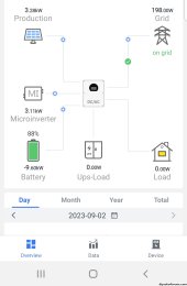
Screenshot_20230902-094805_Deye kolmonen.jpg


The other one has full battery already and is feeding critical loads with 2,1kW while there shouldn't be any critical loads to feed.
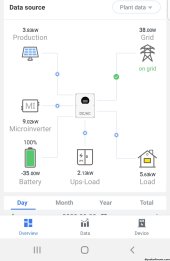
Screenshot_20230902-094912_Deye nelonen.jpg

Any thoughts?
 
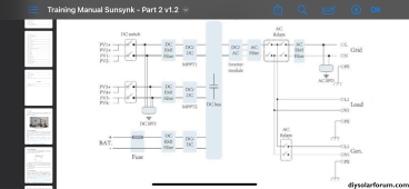
They shouldn’t backfeed each other using the LOAD port, but it’s possible that it’s occurring. Makes sense if you take a look at the circuit diagram:

IMG_3880.png

Since you’re using micronverters, you can have power circulating from GEN to LOAD ports, according to the diagram above.

I advise you to connect both inverters as master/slave, because if any of the inverters loose it’s phase reference, you can loose the synchronism between them.
 
Actually not using microinverters but two Bluesun 15K GT inverters AC coupled through GEN ports. Stating microinverters is just the way how Deye handles AC coupling.

Can't parallel them as master/slave because of different battery chemistries. The other one is using FLA and the other LFP.

My utility connection is 75m away from my "solar corner" so I can't use original CTs. Instead I'm using Eastron md630 modbus v2 meters for each Deye independently to get correct CT readings.
 
The obvious test here is to monitor the LOAD port for current.
Very true. I'll do that although seeing that diagram above I'm pretty sure they are capable sharing some energy. Measuring needs to be timed correctly as they don't share current all the time. At least according to Deye app it seems to happen only when other battery is full and the other is still charging.
 
The obvious test here is to monitor the LOAD port for current.
It seems there is ~5A per leg (230V) when I tested it yesterday so there's some power exchange going on between my Deyes. It seems to help to charge up my other battery when the other one is already full.
 
I don't remember how your batteries were set up but a parallel Deye system MUST be connected to a common battery bank, not separate batteries. As per your post over.
Then it should charge/discharge ALL batteries at the same time.
 
Same fault, bro.
1. When I installed 2x Deye 12k 3phase parallel & 25kWh (connect 2 inverters - main&slave) (follow image 01& 02)
2. And an unexpected results, the home load is Zero, UPS load is 2.8kW although the system is grid mode (not backup mode) (image03)
3. When I removed 01 int ( only 01 ivt running), Home load returned good running mode ( image 04)
I hope the pro engineer can help me this fault
Thanks
 

Attachments

  • IMG_5099.jpeg
    IMG_5099.jpeg
    795.6 KB · Views: 16
  • IMG_5100.jpeg
    IMG_5100.jpeg
    862.9 KB · Views: 9
  • IMG_5079.png
    IMG_5079.png
    124.4 KB · Views: 7
  • IMG_5102.png
    IMG_5102.png
    149.9 KB · Views: 9
Last edited:
Is it possible to somehow backfeed via critical load connection?
Yes
The downside is it has less control over that port.
It can still frequency shift, but can't disconnect completely.
Frequency Shift isn't always fast enough. And unused current can cause damage.
 
Same fault, bro.
1. When I installed 2x Deye 12k 3phase parallel & 25kWh (connect 2 inverters - main&slave) (follow image 01& 02)
2. And an unexpected results, the home load is Zero, UPS load is 2.8kW although the system is grid mode (not backup mode) (image03)
3. When I removed 01 int ( only 01 ivt running), Home load returned good running mode ( image 04)
I hope the pro engineer can help me this fault
Thanks
When in parallel the slave inverter should have a following number on the modbus, 02 instead of 01.
 
e
When in parallel the slave inverter should have a following number on the modbus, 02 instead of 01.
sorry bro, number 2 is same fault. Then I change to “number 1”, ivt display is error Fxx…
I have followed UM of Deye
 

Attachments

  • IMG_5103.jpeg
    IMG_5103.jpeg
    634.4 KB · Views: 4
I don't remember how your batteries were set up but a parallel Deye system MUST be connected to a common battery bank, not separate batteries. As per your post over.
Then it should charge/discharge ALL batteries at the same time.
Deyes are electrically parallel, but not programmed to work as parallel (both are masters, no communication between them). I have LFA and LFP batteries so can't charge them as single battery.
 
Same fault, bro.
1. When I installed 2x Deye 12k 3phase parallel & 25kWh (connect 2 inverters - main&slave) (follow image 01& 02)
2. And an unexpected results, the home load is Zero, UPS load is 2.8kW although the system is grid mode (not backup mode) (image03)
3. When I removed 01 int ( only 01 ivt running), Home load returned good running mode ( image 04)
I hope the pro engineer can help me this fault
Thanks
No fault. I really want it to work this way, I just didn't believe this is even possible. Actually even Deye engineers didn't know what's going on with my disconnected UPS load.
 
Yes
The downside is it has less control over that port.
It can still frequency shift, but can't disconnect completely.
Frequency Shift isn't always fast enough. And unused current can cause damage.
Does it have to have any control? I mean that port is disconnected by ATS and only connected to main panel when utility is down. Only my Deyes are connected to each other by it (LOAD-port) all the time. Frequency shift controlling my AC coupling should be done by GEN-port, not (UPS)LOAD-port.
 
No fault. I really want it to work this way, I just didn't believe this is even possible. Actually even Deye engineers didn't know what's going on with my disconnected UPS load.
Why? UPS load is in back-up mode, home load is grid load. ATS between 2 modes. Please, make it clear. Actually, I don’t know this, bro
 
Does it have to have any control? I mean that port is disconnected by ATS and only connected to main panel when utility is down. Only my Deyes are connected to each other by it (LOAD-port) all the time. Frequency shift controlling my AC coupling should be done by GEN-port, not (UPS)LOAD-port.
Frequency shift should happen on both (gen and loads) ports.
But only the gen port can disconnect, if needed.

I mean that port is disconnected by ATS and only connected to main panel when utility is down.
An external ATS?
That might be ok.
 
They aren't designed to be connected this way. (Output to output) if battery is full,there is nowhere to send excess power. (Before frequency shifting can get control)
It would be safer to only parallel the inputs.
Or connect the second input to the first output. (In succession)
 
When you say "frequency shift", do you mean "phase shift", of do these units actually adjust the frequency? Slight frequency shifts can be thought of as a continuous phase shift, but do they support, say matching 50Hz and 60Hz feeds? That's a pretty serious adjustment.

My assumption has been that any phase (frequency?) shifting was done in the inverter, but this discussion seems to indicate that there's more to it than that. Do they really support aligning the phase of line and generator inputs? My brain starts to hurt if you start back feeding loads that could be at a different phase, and having to align with that as well ... in two different inverters, so I'm not even going to go there.
 
Back
Top