TheTallOne
New Member
Newbie here, please be gentle.
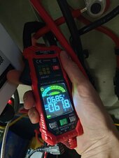
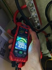
TLDR: My paralleled DIY battery banks are discharging and charging at different rates. The master pack at 100A, the slave at about 60A. This ratio seems to be consistent, I do not know the cause.
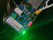
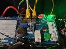
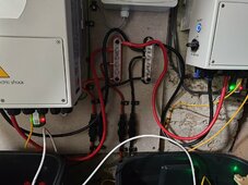
I have a pair of DIY 48v/16s/320aH battery banks, both run by Seplos 200A BMS 10e (one has bluetooth, the other doesnt, other than that they're identical). I have set identical settings for both BMS and then paralelled them with DIP switch settings according to the manual. However, when discharging (and I assume charging, though I haven't checked), one pack takes more load than the other, at a ratio of 100/60. This is a problem because a)I don't want to wear one pack more than the other and b) my DC fuses are 125A, which means my inverters (rated to 115A) can't export at max capacity without blowing the fuse on the master pack.
The inverters are a pair of Sunsynk ECCO 5.5kw, in parallel and as far as I can tell, working fine.
DC cables are the same lengths (to within a couple of cm) on both packs, connections all seem to be good. I feel like I'm missing something obvious here but I cannot think of it. HELP!
My only thought is that I wonder if my DIP switch settings are correct. My reason for wondering is that when I paralleled my inverters, the slave inverter just inherited all the settings from the master. When I paralleled my BMSes, it didn't, I had to connect to the slave manually and set everything, then set the switches for paralleling. But there's two possible settings, CAN and RS485. I'm using the CAN settings, is this where I've gone wrong?
Many thanks in advance!
Jon
TLDR: My paralleled DIY battery banks are discharging and charging at different rates. The master pack at 100A, the slave at about 60A. This ratio seems to be consistent, I do not know the cause.
I have a pair of DIY 48v/16s/320aH battery banks, both run by Seplos 200A BMS 10e (one has bluetooth, the other doesnt, other than that they're identical). I have set identical settings for both BMS and then paralelled them with DIP switch settings according to the manual. However, when discharging (and I assume charging, though I haven't checked), one pack takes more load than the other, at a ratio of 100/60. This is a problem because a)I don't want to wear one pack more than the other and b) my DC fuses are 125A, which means my inverters (rated to 115A) can't export at max capacity without blowing the fuse on the master pack.
The inverters are a pair of Sunsynk ECCO 5.5kw, in parallel and as far as I can tell, working fine.
DC cables are the same lengths (to within a couple of cm) on both packs, connections all seem to be good. I feel like I'm missing something obvious here but I cannot think of it. HELP!
My only thought is that I wonder if my DIP switch settings are correct. My reason for wondering is that when I paralleled my inverters, the slave inverter just inherited all the settings from the master. When I paralleled my BMSes, it didn't, I had to connect to the slave manually and set everything, then set the switches for paralleling. But there's two possible settings, CAN and RS485. I'm using the CAN settings, is this where I've gone wrong?
Many thanks in advance!
Jon