diy solar

diy solar

Raspberry PI Power Supply

lboucher26

New Member
Joined
Sep 24, 2022
Messages
59
Hi All

Figured i would just post my story, as it might help someone.
So i had Solar Assistant setup on an Orange PI, for a bit over a year.
It was running from an SD card.
Then it suddenly failed.
At first i thought it was the SD card, but after lots of troubleshooting, i think the card was fine... I think the board just failed...
I cannot get it to start with multiple fresh and reformatted SD cards... Just no LEDs at all regardless of what Power supply i use...

So i setup an old Raspberry Pi3B in its stead.
And got a Solid State USB SSD setup.


Started experimenting.
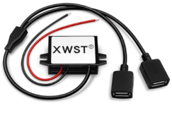
I was using a power supply like this:
1714918797437.png
So that it was powered direct from the solar battery bank.
Unfortunately, this device is providing like 4.9 VDC, and does dip to like 4.7
Which is evidently enough to make the PI throttle as shown by this command.
vcgencmd get_throttled
Which is kinda annoying because it was drawing less than half an amp... As measured with one of these.
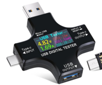
1714918745415.png

I could get it to run unthrottled by using my best phone charger which output 5.1 VDC

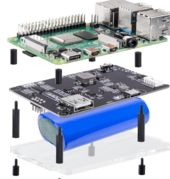
I decided to try a Sunfounder USB UPS.
1714918881864.png
Unfortunately... No dice, if i plug in the power supply from the solar batteries the output voltage drops to 4.9
Unplugged it does output 5.1 and the pi starts as desired.
I'm probably going to power it from Mains with the UPS and call it a day.


SEPERATE ISSUE, in same saga....
When i changed from a SD Card to a USB SSD.
Suddenly i realized that IF my EG4 6000 inverter was plugged into the Raspberry PI and i applied power to the pi... I just would not start.
If i unplugged the inverter, it would start.
I also have my LifePower batteries plugged in via USB RS485 adapter. That doesn't seem to affect the PI at all.
I did notice that it seemed like power was flowing from the Inverter to the PI via that USB connection... So i was wondering if that was causing an issue on boot.
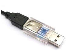
I did get a USB power blocker
1714919373198.png
That appears to have had no effect.

Working with ChatGPT.
I updated the PI using these commands
sudo apt update
sudo apt full-upgrade
sudo rpi-update
No effect

I added usb-storage.quirks=0dd8:0562:u to the boot command line.
Trying to force it to use the right USB device to boot.
No effect...
And to clarify, the PI will not recover from a full shutdown and power cycle NOR via a reboot if the Inverter is plugged in.
Only other idea i have is to hookup the inverter data line to a relay... Which seems ridiculous...

Ohh and yes, if i power up the PI, with the good cell charger connected, let it boot happy, no throttling, then switch to Solar Power VDC to USB charger, it then throttles.

Any ideas or thoughts on this whole debacle are welcome.
 
WAG, but ...

Get a stable power supply (smps wall wart) and power the RPi (or whomever's PI) through that. With that power in effect, maybe not as much grief from power trying to come in over USB, and RPi not liking that (not booting).

Adding more shields and such, and replacing SD with SSD means more power requirements ...

All feels like power issues still in there somewhere. Try the dedicated wall wart (sized with enough amps for all pieces) and see if things settle down.

Hope this helps ...
 
I would trust something like this:

Maybe a 48v to 12v, and then use a high quality 12v to usb to provide known clean power.

I went round and round on powering internet and monitoring 24/7. I was thinking direct from battery, but if I took the battery off line, it would all go down. I ended up putting the standard AC power supplies on a spare APC Back-ups, and use a Victron Orion TR 48/12-9 as the "battery" to the ups. The Ups "complains" about the battery, but runs fine when I pull the ac plug. Power draw of all the equipment is 40 watts, well within the 100 watts of the Victron, and 350 watts of the ups.
 
I know the Pi 4B won't start up if there is any voltage on the USB data lines. Possibly the 3B has the same issue and there is some leakage back from your inverter.
 
USB is not isolated at all (neither power nor data) so it behooves you to understand how to work around it.

RS485 adapters are available in both isolated and non-isolated flavors. Given how low bandwidth it is, I'm still surprised that the standard recommendation isn't to always use isolated one.

This weekend I successfully switched my Pi4 to run off a 5V DC UPS. Didn't carefully read the specs before buying it, and ended up with a unit that only promises 5V/2A. Was able to start up fine.

The backup plan (apart from mailing it back) would have been to buy a small 5V/3A buck converter and run it off the 12V rail.
I have close to no idea what u are talking about?
What 12 volt rail? I have 1 48vdc lipo4 battery.
I stated I bought a power blocker which just disconnects the 5 volt line on the USB cable. I know the inverter was sending power to pi because if I kept that usb line plugged in. The ethernet link light would keep flashing even if power was off.

The rs485 adapter isn't causing me any issues at all.
 
I have close to no idea what u are talking about?
OK, sounds a little aggressive, but I'll continue to help since you have a decent Linux shell understanding and seem to have done a lot of homework already.

What 12 volt rail? I have 1 48vdc lipo4 battery.
I was referring to the DC UPS that I bought, which was underspecced on 5V. If the 5V browned out for the RPi4 , then either I return it or add a 12V->5V buck.
I stated I bought a power blocker which just disconnects the 5 volt line on the USB cable. I know the inverter was sending power to pi because if I kept that usb line plugged in. The ethernet link light would keep flashing even if power was off.
Disconnecting the power is good, sure.

USB data lines are not transformer isolated (unlike EG Ethernet) so you can get some bleed through those. Just because it is differential D+/D- signaling, doesn't mean you're immune from a problematic voltage level relative to how the RPI is is powered.
The rs485 adapter isn't causing me any issues at all.
OK, cool.

Is the 48V->5V converter topology non-isolated positive reference, non-isolated negative reference, or isolated (and therefore can be referenced whichever way you like)? Maybe there is a superior option out of the three, that plays nicer with having a USB connection. If you switch to 120V->5V wall wart it is isolated. Isolated will probably give you the fewest problems. Isolated is mandatory on AC-DC but for DC-DC it can be omitted to save $$$ and allow more power conversion output.

Is there an alternate data path you can use instead of the USB connection? (You did not link the EG4 6000 that you are using and I wasn't able to guess with the time I allotted to searching for candidates via Google.They've sold several 6000 models).
 
Sorry about that... What can i say, had a interesting day that day with some people at work, it bleed over... My Bad.
Anyways.

agreed on USB data lines, although i assume the issue is with the PI not detecting the "Right" usb port to use as the drive... Since it was wording with SD card...

I have absolutly zero idea on specifics of DC to DC, its just this i bought off amazon.
https://www.amazon.com/gp/product/B09GJRKNQK/ref=ppx_yo_dt_b_search_asin_title?ie=UTF8&th=1

I did buy one of these and intend to try it.
https://a.co/d/dZ3fH1U

Interestingly i am now having issue with the PI just stopping... Even when plugged into a very good wallwart putting out 5.1VDC under load. I haven't investigated logs or anything yet...
I think i am going to try going back to SD card and see if its stable on the wallwart... Then try adding in the new DC to DC and the UPS.

I am using this inverter

To my knowledge there is no other way to connect solar assistant other than the USB.
It has wifi... But it sucks.
 
Maybe not what you are looking for, but IIRC, one of the eg4 aio's has an odd pinout where there is 5v on one of the wires that normally does not carry voltage. That is what I assumed was happening in the first post when turning on the aio.
 
The PI has a bad rep when it comes to its 'USB power input' it demands 5vdc, but the USB spec is 4.5v to 5.5vDC unloaded, so you can have a 'legal' USB power supply that won't run a Pi...

Plus many 5vdc supplies are woefully underfiltered and will add 'hum' to the output supply, in which case added filter capacitors may be needed to make the Pi run happily...
 
You can also check the CPU stuff on the Pi, here are some snippets of Python code:
You can also watch the power LED, it'll flash on power supply anomalies, as will the raspberries in the upper right of the HDMI video output.

# Temperature in degrees C to .001
def measure_temp():
with open("/sys/class/thermal/thermal_zone0/temp", "r") as tf:
return (float(int(tf.read())/1000.0))

# Frequency in GHz, resolution to Hz, but not sure that's useful
def measure_freq():
freqHz = os.popen("vcgencmd measure_clock arm").readline()
freqHz = re.sub(r'\(.*\)','',freqHz) # remove the parens and everything between
freqHz = freqHz.replace("frequency=","").strip()
return float(freqHz)/1e9

# DC Volts on the CPU, resolution to 4 decimal places
def measure_volts():
volts = os.popen("vcgencmd measure_volts").readline()
volts = volts.replace("volt=","")
volts = volts.replace("V","").strip()
return float(volts)

# (tuple) of current and past status wraning flags as integers 0-15
def throttled_status():
StatusNow = 0
StatusEver = 0
throttled = os.popen("vcgencmd get_throttled").readline()
tInt = int(throttled.replace("throttled=",""),16)
StatusNow = tInt & 0x0f # mask off low order bits
StatusEver = tInt >> 16
return (StatusNow,StatusEver)

# list[] of 1,5,15-minute load averages
def measure_load():
with open("/proc/loadavg", "r") as lf:
load_list = lf.read().split(' ')
return (load_list[:3])

# return a list of strings for throttled bits
ThrottledStrings = ["Under-voltage","Arm frequency capped","Throttled","Soft temperature limit"]
def throttled_message(status):
rtnStr = []
index = 0
while status: #if there are any (more) bits high
if (status & 0x01): # if it's this one
rtnStr.append(ThrottledStrings[index]) # add to string
status = status >> 1 # either way, shift down
index += 1 # and bump the index
return rtnStr

CPUtemp = measure_temp()
print ("Temp: ",CPUtemp)
CPUfreq = measure_freq()
print ("GHz: ",CPUfreq)
CPUvolts = measure_volts()
print ("{} DC Volts".format(CPUvolts))

(StatusNow,StatusEver) = throttled_status()
print ("Now: {:04b}, Ever: {:04b}".format(StatusNow,StatusEver))

if throttled_message(StatusNow):
print ("Now: ",throttled_message(StatusNow))
else:
print ("No current warnings")
if throttled_message(StatusEver):
print ("Ever: ",throttled_message(StatusEver))
else:
print ("No past warnings")

CPUla = measure_load()
print ("Load: ",CPUla)
 
Following this thread with interest. I've had a lot of trouble finding stable power sources (other than specific AC wall warts) for RPi and similar...
 
There are some 48 volt to USB adapters on AMZ, solar assistant reads the CPU temperature and displays it on their application.
 
Back
Top