diy solar

diy solar

Reading Basic Wiring Diagrams

JeepHammer

Solar Wizard
Joined
Nov 15, 2019
Messages
1,149
This is something I did for vehicle wiring diagrams.
An Electrical Schematic is a very precise technical drawing of electrical circuits.
A Diagram, or Pictogram, shows representations of the components you will be using, and showing the wiring in between.

'CIRCUIT', BY DEFINITION, MAKES A 'LAP'.
A Direct Current (DC) Circuit Starts, and Ends at the same device (battery, charge controller, PV/wind/hydro, etc).
If that Circuit (Lap) is not completed, your Circuit is not complete and won't work.
A switch, relay, etc. 'Opens' the Circuit, stopping the Circuit from completing, giving you control of the devices.
A 'Closed' Circuit is a functioning device.
So when a switch is 'Off', that means the Circuit is 'Open',
When a switch is 'On', that means the Circuit is 'Closed', a closed 'Loop' or closed 'Circuit'.


While this is automotive related, it pretty common for all wiring diagrams/picrograms.
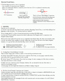
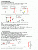
WiringBasics01.gif

WiringBasics02.gif

WiringBasics03.gifWiringBasics03.gif
 
Last edited:
Circuit Protection!
If you don't use circuit protection, take your project someplace safe and burn it down in controlled conditions so it doesn't take your vehicle and/or house with it. This is not an exaggeration.

Start with wire/conductor size that will carry the current (in Amps) for the electrical Load,
And simply use a wire/conductor size that will support the Load.
Use fuses/breakers as close to electrical 'Source' (battery, charge controller, ect.) as is practical.

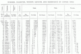
Find the Load in amps, look for that Amp Load in the 'Amps' column (round up), and look far left for the minimum SAFE wire gauge size. This is the Brown & Sharpe scale the American Wire Gauge Standard is based on.

B&Sscale01.gif

While the correct size wire/conductor means the electrical Load will be supplied safely,
There are other factors at work,
Malfunctions (short circuits) and mechanical damage (wires getting pinched, rubbed through, etc) MUST be considered!
Some of these real world problems will WAY overload the wiring, and to be safe you MUST anticipate failures in equipment and mechanical damage.

A Fuse/Circuit breaker in the line, as close to the power source as is practical, protects the WIRE going to the LOAD, and returning from the load.
An example;
A charge controller/battery charger,
*IF* that charge controller malfunctions and throws 80 Amps at batteries rated for 30 Amps, the fuse or circuit breaker protects the WIRES first, but also protects the batteries from an 80 Amp 'Surge' in the line from the charge controller.

Another example;
A headlight.
Two larger gauge wires go through the glass, and a small filament wire connects between the two, heats up, makes light.
That filament is supposed to draw 5 Amps.
You hit a deer... The light breaks and the two larger wires get bent/connected...
Now you have a 40 Amp draw on a 5 Amp circuit, and the supply circuit starts to heat up.
Without circuit protection, the wires will heat to glowing hot, melt insulation, and can very well start a fire.
With circuit protection, the fuse or breaker simply does it's job and protects the wiring until you get a new, properly functioning bulb. (There is a reason every factory headlight switch has a circuit breaker built into it)

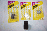
Most of the common circuits you will build will be lower Amperage, and there is no sense in reinventing the wheel,
The automotive market will supply 95% of what you need for common circuits.


HL06.gif
 
Last edited:
A Power Relay is designed to be a remote 'Switch'.
It can be used in a number of ways, AC can switch DC, or the reverse, and keep AC/DC circuits separated,
Low voltage/Low Amperage (small wire) can be used to control High Voltage/High Amperage circuits,
One control circuit can open/complete several other circuits at once, among other things...


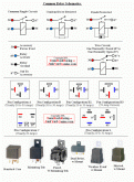
Relay.gif

The least expensive and most commonly available relays will be automotive, and this is what they look like, terminal connections, etc.

relaygraphic01.gif
 
Last edited:
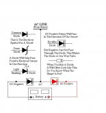
Diodes, Don't have these images found just quite yet...
A diode is a Polarity Sensitive (Positive or Negative) sensitive 'Gate Valve' for electrical current.
I'll get to this more when I find the diagrams for examples.


Diode.jpg
 
Saving more space, but this is it, if you have something to add about something above,
NOT something specific/questions,
But something to build on the basics,
Quote the section in the reply, and build on the basics!

Simple circuits, common parts, common applications,
It's 'Simple' to the educated, but the idea is to share education/application, so keep it SIMPLE!,
And have fun! :)

----------

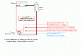
This is a compound circuit, in this case it's the engine starter circuit on an old Jeep.
The Key Switch is the 'Activation' (power source) for the small wire/low amps circuit so you don't have to run battery cable size wire into the passenger compartment,
And the starter 'Solenoid' (common language usage) is actually a big Relay for High Amperage to the Starter Motor (electrical load).
Key switch is the 'Control' circuit, the 'Solenoid' (Relay) is the remote switch for high amperage.

dualbatt01.gif
This also shows circuit protection for the battery voltage feed TO the fuse block,
And circuit protection for the alternator/battery wire. (Fusible Links/Fuse Wire)

Notice a detail,
The full time battery connections, the full time 'Hot' wires are solid bright Red.
After a Switch/Relay, Most manufacturers (and me) use a 'Red' wire with a white stripe (called a 'Trace') to identify a power wire that is on a switch.
A complete diagram will have the wire gauge size (see above), the color (Red, Blue, etc) and trace color ( w/Blue, w/White, etc).
The 'Trace' can also be small bands of heat shrink on the wire ends at the terminal ends.
For instance, a White wire can have a red or black band of heat shrink at both ends, that will let you pick it out of a harness with other 'White' wires.

When your drawing becomes actual circuits, using all one or two colors becomes confusing, so as you build use traced, heat shrink bands, etc. to distinguish the different wires in a bundle.
Don't forget to update your diagrams! A well made circuit may last for decades, and a good diagram lets you refresh your memory and find wires quickly, it's the 'Road Map' of your circuits.

----------
 
Last edited:
Back
Top