diy solar

diy solar

Solar house generator I started DIY back in 2000 - My path from Trace to Xantrex (on FLA battery) to XW Pro inverters on Tesla Model S batteries

Or far, far more.

(I need to spend more time building out my new place. Paperwork keeps holding me back.)
 
ordered a Tesla Model S module today, #14 for 70kwh of storage, $514 dollars
growing the pack over time as the money becomes available
goal is 100kwh
 
Last edited:
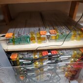
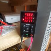
tesla battery module #14 arrived today (one on the right), put it in series with #13 and they are now charging to 48 vdc with a 60v lab power supply once that is done will add to the busbars when the pack is also at 48v (system off of course)

cost $514, better than the $1300 I paid for 1st one

70 kwh now

last pair installed Sept 2022

interesting note: #14 is not used, rather it is factory overstock

title

TESLA MODEL S X BATTERY 5.2KWH 24V 250AH SOLAR CELL MODULE PACK LITHIUM EV RV​

Never installed Factory Overstock

description

"New other (see details): A new, unused item with absolutely no signs of wear. The item may be missing the original packaging, or in the original packaging but not sealed. The item may be a factory second, or a new, unused item with defects. See the seller’s listing for full details and description of any imperfections."

so maybe. we shall see
It is a later version. Has newer balance ribbon and not individual wires of the older version, so at least 2018 vintage

20240409_161157.jpg

20240409_161203.jpg
 
Last edited:
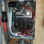
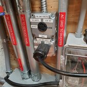
Today I finished a refactoring task on the Subpanel GRID, and swapping out PVC conduit to EMT

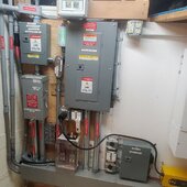
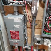
Here is the inside of the Subpanel GRID. 2 AWG wire from up stream panel, and 1 AWG for downstream circuits (had extra 1 AWG so I used it)

replaced 100 amp QO panel that had 6 spaces for a 8 space QO 100 amp panel
this will allow for a total of 4 240v breakers, instead of 3. Thus giving 2 L14-30r's availability

common NEUTRAL without a NEUTRAL loop
one run of NEUTRAL to XW Pro
one run of NEUTRAL to Transfer Switch's NEUTRAL bar.

Transfer switch feeds just one NEUTRAL to critical loads panel and NEUTRAL is not 'switched'.
That is the reason for a COMMON NEUTRAL without loops

same for ground, no loops
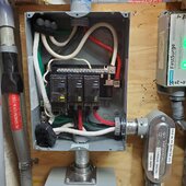
20240411_124604.jpg

I also am upgrading from ONE GRID fed L14-30r receptacle to TWO L14-30r receptacles, since I have 2 Chargeverters.
I have 2, primarily for backup protection (one is none....) and for faster grid charging when needed
The XW Pro controlled automatic recharge due to LOW BATTERY only controls ONE L14-30r receptacle

and in the middle are the 2 100 amp breakers for the transfer switch and input to the XW Pro inverter
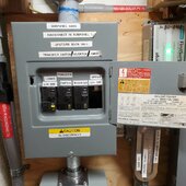
20240411_132608.jpg

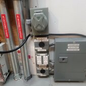
here are the 2 boxes for the 2 grid L14-30r's
the 30amp GFCI breaker and 3/4" MC flex conduit are in flight due to arrive Thursday or Friday

Notice LOCK on transfer switch. Need it, since there is no safety panel behind the front cover

To the lower right are the 2 SSR relays controlled by the XW Pro AUX contactor, for LOW BATTERY events
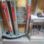
20240411_124620.jpg

the grid dual L14-30r's are similar to the Generator dual L14-30r's setup
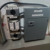
20240411_124628.jpg

and final overall pictures
20240411_125930.jpg

20240411_125954.jpg
 
Last edited:
As mentioned in prior posts, I am doing a new design for my system to upgrade from 125 amp service to 200 amp service

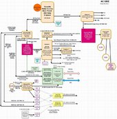
I currently have a 125 amp service that I installed back in 1998. Through that service I run a 100 amp circuit to my whole house solar generator. I have added a 60 amp run for a EV charging port on the grid only panel. Even though my loads have been optimized with efficient operation, I can see future issues. So I have modified my one-line schematic of my current system (which is posted in the 1st post of this thread if you wish to compare with the new design) for a future 200 amp service install.

Should be a simple process all outside for step 1. I do not need to immediately move the 100 amp solar run, just swap the outside service panel

as also mentioned prior, the biggest issue is the $2500 power company impact fee for the upgrade, plus the permit fee.
Our hobbies do cost, do they not?

Thompson-AC-Phase-240v 200amp.jpg


.
 
Last edited:
Flex MC conduit arrived today with end adapters, installed the GRID L14-30r receptacles and their wires up to panel..............

20240412_224556.jpg

got LOWER receptacle wired up

BUT, no 30 amp GFCI breaker..........arriving on monday

so wires for UPPER receptacle are just hanging out awaiting

20240412_224604.jpg

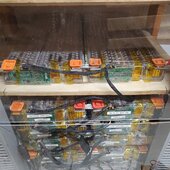
FINALLY got battery modules #13 and #14 charged to 48 volts, then waited this evening for battery voltage level to drop down 48 volts and installed the 7th row of modules, 70 kwh of battery, 1640 amp-hours

installed and got the safety plexi-glasss shield installed again

20240412_224623.jpg
 
on a roll these past few days on finishing tasks:

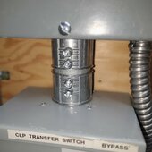
re-installed the generator inter-lock and the inlet L14-30p plug into my CLP. This is my 2nd attempt


it has now become my LAST backup in case of total system failure

if I lose the GRID, my battery or my inverter, I can power the house directly from generator as if I had no solar at all

Inlet plug now right above the generator receptacles. Get my short 30 amp patch extension cord and plug it in and flip the interlock and I am good

20240413_171305.jpg
 
corrected an NEC error

after upgrading from 1-1/4 PVC conduit to 2" EMT conduit, the new conduit has more capacity

therefore on my 8 space grid panel feeding to the Transfer switch AND to the inverter, I have removed the conduit to the inverter and moved those conductors there were there to the 2" lower left conduit where just the 240 legs came into the transfer switch. Now 5 conductors and a ground all go through that lower left conduit. This then meets the NEC requirement where all conductors must pass in the same conduit

here is the 8 space panel with the old feeder to the inverter leaving the lower right side of the panel

OLD/BEFORE

20240411_124604-jpg.208725


and here is the new current configuration of the same panel - both GFCI 30 amp breakers also installed

AFTER/NEW wiring

20240501_175128.jpg

notice the new short 2" emt conductor, so that I can pass 2 more #2 conductors to the inverter through the transfer switch

20240501_175248.jpg

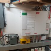
pic of both the grid panel and the transfer switch opened up. Nice having the conduit that was in the space on the right, GONE


20240501_164647.jpg

and over all pic, including both of the chargeverters installed.. My son got his V2

20240501_192052.jpg
 
I recently installed my 14th Tesla Battery Module, well I re-found a web page describing a LARGE whole house solar system that has 36 Tesla Battery Modules


and his build thread https://teslamotorsclub.com/tmc/thr...th-a-model-s-battery-pack-at-the-heart.34531/

as a software engineer, he wrote his OWN BMS controller for the stack

I AM impressed

here is it's mounting rack - I like it, might copy it for my goal of 20 modules

2015-03-25-18-55-28-1920-jpg.75891
 
Last edited:
back in feb 2020 I implemented my "Full Battery Diversion" load subsystem

at that time, my system was a 48 volt battery and 48 volt solar arrays, with a 5000 watt Xantrex SW+5048 120v only LF inverter.

I installed 2000 watt 120v coils. I used those from that point onward, even after I installed a 240v XW Pro inverter in november 2022 - until this past month. I attacked this pending TODO task

I have now upgraded my coils to 3000 watt 240v and re-wired for 240v operation. I am now heating my water with excess PV solar power in the 2 50 gallon pre-heaters. These feed the tankless gas water heater. The water gets hot enough that the gas tankless does not even fire up the burner, but just passes the hot water on through

another upgrade task completed. After this has been done, I have bumped my maximum kwh production from 35 kwh to 45 kwh, on a good sunny day - but not yet entirely cloud free. I hope to have some fully cloudless days ahead and maybe hit a 50kwh day

charging the morning battery to full and running loads in the house consumes about 25kwh a day
 
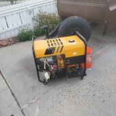
Fixed/upgraded my $50 Winco 8000w 2 cylinder 16hp brushless generator made in 1997

link to 1st post about generator

link to how capacitors are used instead of an AVR


Replaced the 40uFD caps (3) with 3 50uFD caps to boost the voltage

old results with the 40uFD were

No load 120v
3000 watt load 112v
4000 watt load 109v
5000 watt load 107v

new 50uFD caps installed

No load 127v 62hz
3000 watt load 116v 60hz
4000 watt load 115v 59hz
5000 watt load 114v 59hz

great improvement.

the generator feeds Chargeverters so even with the older lower voltages things would be fine, but I wanted the generator to produce near 120v per leg

all on propane


Winco 2cyl 16hp 8000watt dual fuel generator - yeah, someone sold it for $50 because its power head would not generate power. I believe someone misdiagnosed it as a "bad" power head without investigation, with a huge cost to replace it. So the owner basically dumped it on the classified and I got lucky.

The issue was caused by a simple #16 shorted/broken AC feed-line to the 3 capacitors.

holding-fried-cap-lead-jpg.172987


Fixed that line and the generator began making great power and works great. My super deal for the year

the most power I have gotten out of it, is 6300 watts without the engine beginning to stall out. again on propane and we are at 5535 ft elevation. So I think that is pretty good output and enough to run the 2 Chargeverters at 3100 watts each when needed

20230926_192050.jpg
 
Last edited:
Back
Top