diy solar

diy solar

Solis S5 / Puredrive / Zappi

Cooperman

New Member
Joined
Mar 12, 2024
Messages
5
Location
Northampton
S5-EH1P5K - 3 x Puredrive 2 5kw DC - 2 x Zappi
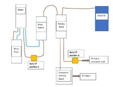
I am having issues with my system, it has always drained batteries into Zappi unless inverter is charging, so I have finally had a second zappi installed and the feed to both Zappis moved to their own external consumer unit from a Henley block. I thought moving the CT for the inverter to the feed to the house consumer unit would cure the problem as in theory the inverter would no longer see their draw. As soon as the Inverter CT clamp is moved to (position 2) after the after Henley block it either starts to charge the batteries or it turned around it discharges to grid. If it is in position 1 it functions correctly but sees the Zappis and throws the battery into the car. System has Eastron Meter
Inverter Settings
Meter type "Eastron 1ph Meter"
Install on "Grid"
S5.jpg
 
Welcome!

CT position 2 would work, but only if the AC-grid connection to/from the Solis is connected on the home CU side of the CT Clamp. The reason is that the Solis will attempt to keep grid import to zero (based on the values it gets from the CT) if the Solis can provide enough power to meet the house demand.

So, basically you will need the connection to the Zappis to become before the CT clamp and before the connection to the Solis.

Off the top of my head, the other two options would be:-

a) if you are only charging the car on a cheap rate at night, then configure the Solis to either charge for the whole cheap rate period, or set a discharge time period in the TOU settings with a discharge current of 0A. That will prevent the Solis from powering the house at that time. Be careful not to overlap charge and discharge times as that will confuse the Chinese software!

b) if you have the skills, implement a MITM controller, between the Eastron and the Solis to more finely control the Solis. @peufeu has developed a system to do that - see his thread here...

Thanks,
I have Octopus intelligent which can schedule charging hours at any time, and running to the inverter to set a new charge schedule the deleting it was tedious at best, hence the recent work. I charge the batteries every night from grid as I get twice as much for export to what I pay import, but I want a set and leave system. Why does the system/Invertor charge/discharge when the CT is moved from P1 to P2, there was only a house base load, but the system went crazy exporting or charging the batteries (depending on CT orientation) and I don't understand why it interpreted the CT reading so differently for the same house draw?
 
Why does the system/Invertor charge/discharge when the CT is moved from P1 to P2, there was only a house base load, but the system went crazy exporting or charging the batteries (depending on CT orientation) and I don't understand why it interpreted the CT reading so differently for the same house draw?

It went crazy because you broke the "closed-feedback-loop" by having the CT clamp on the wrong side of the inverter's connection.

With it in position 2, as per your diagram, the inverter will try and make the reading zero, by generating enough power to get the value down.

Let's say the house usage is 500W. The inverter will receive that value and output 500W from your batteries / PV to compensate.
But because you have the Solis on the wrong side of the CT clamp, the value the Solis receives from the CT won't change.
So at that point the Solis is generating 500W and powering your house, but it is still seeing a usage of 500W.
The Solis will therefore assume that the house load must now be 1000W, so it will increase its output to 1000W. (so you are using 500W and exporting 500W)
But the Solis is still being told that there is 500W which needs to be powered - effectively the Solis thinks you are now using 1500W, so it will increase its output to 1500W...
This will continue for a few 10's of seconds at which point the Solis will be generating its max of 5000W, but still thinks its not enough.

The same principle will happen in reverse if you swap the CT direction.

So if I understand above the Solis connection would be removed from the Henley Block and added to the feed from the Henley block to the consumer unit and the CT in position 2 but between the Henley block and new connection?
 
There's this setting:

1710286716842.png

If you set it to "Grid" it will try to zero the meter reading as SeaGal explained. This only works if the CT reads the Solis' own power, so the inverter has to be on the load side of the CT not the grid side, in other words CT at position 1.

If you set it to "Load" it uses a different algorithm: it reads the meter and attempts to export the same power to compensate. So if you install the CT at position 2, you have to configure it to "Install on Load" mode on the above screen. Then it will only discharge the batteries to power the house, not the car. It has to be the correct polarity, when it is set properly you will see the correct reading for power used by the house on the display. So you can use this mode to avoid re-doing your wiring.

The drawback of position 2 is: if you plug your car on a sunny day, the inverter won't know about it. If you already set it to export all the power it can because you're selling it, that's not a problem, the exported power will go into the car instead of into the grid... but since the inverter doesn't know the car is charging, it will not stop charging its battery in order to charge the car instead. Inverter and car will run independent of each other, the only link being the utility meter.

If you're running zero export or another kind of export limitation then position 2 is not a good option because then the cars will charge from the grid even if there's sun. But if you solve that problem by making the inverter aware of the power used by the car by moving the CT to position 1, then it will also dump the battery into the car...

I'm always amazed at how good all these "smart" devices are at being as incompatible with each other as they can and generally doing what they want which is almost always not what you want 🤣
 
Last edited:
If you set it to "Load" it uses a different algorithm: it reads the meter and attempts to export the same power to compensate. So if you install the CT at position 2, you have to configure it to "Install on Load" mode on the above screen. Then it will only discharge the batteries to power the house, not the car. It has to be the correct polarity, when it is set properly you will see the correct reading for power used by the house on the display. So you can use this mode to avoid re-doing your wiring.
(y) good point - I'd forgotten about that as an option.

I'm always amazed at how good all these "smart" devices are at being as incompatible with each other as they can and generally doing what they want which is almost always not what you want 🤣
... thank goodness for a RPi and some RS485 adapters then ;)
 
There's this setting:

View attachment 201786

If you set it to "Grid" it will try to zero the meter reading as SeaGal explained. This only works if the CT reads the Solis' own power, so the inverter has to be on the load side of the CT not the grid side, in other words CT at position 1.

If you set it to "Load" it uses a different algorithm: it reads the meter and attempts to export the same power to compensate. So if you install the CT at position 2, you have to configure it to "Install on Load" mode on the above screen. Then it will only discharge the batteries to power the house, not the car. It has to be the correct polarity, when it is set properly you will see the correct reading for power used by the house on the display. So you can use this mode to avoid re-doing your wiring.

The drawback of position 2 is: if you plug your car on a sunny day, the inverter won't know about it. If you already set it to export all the power it can because you're selling it, that's not a problem, the exported power will go into the car instead of into the grid... but since the inverter doesn't know the car is charging, it will not stop charging its battery in order to charge the car instead. Inverter and car will run independent of each other, the only link being the utility meter.

If you're running zero export or another kind of export limitation then position 2 is not a good option because then the cars will charge from the grid even if there's sun. But if you solve that problem by making the inverter aware of the power used by the car by moving the CT to position 1, then it will also dump the battery into the car...

I'm always amazed at how good all these "smart" devices are at being as incompatible with each other as they can and generally doing what they want which is almost always not what you want 🤣


Thanks I will give this a go when I get home Friday, it certainly an easier fix if it works.
Solar to Zappis is not required as exporting all Solar due to tariff
 
There's this setting:

View attachment 201786

If you set it to "Grid" it will try to zero the meter reading as SeaGal explained. This only works if the CT reads the Solis' own power, so the inverter has to be on the load side of the CT not the grid side, in other words CT at position 1.

If you set it to "Load" it uses a different algorithm: it reads the meter and attempts to export the same power to compensate. So if you install the CT at position 2, you have to configure it to "Install on Load" mode on the above screen. Then it will only discharge the batteries to power the house, not the car. It has to be the correct polarity, when it is set properly you will see the correct reading for power used by the house on the display. So you can use this mode to avoid re-doing your wiring.

The drawback of position 2 is: if you plug your car on a sunny day, the inverter won't know about it. If you already set it to export all the power it can because you're selling it, that's not a problem, the exported power will go into the car instead of into the grid... but since the inverter doesn't know the car is charging, it will not stop charging its battery in order to charge the car instead. Inverter and car will run independent of each other, the only link being the utility meter.

If you're running zero export or another kind of export limitation then position 2 is not a good option because then the cars will charge from the grid even if there's sun. But if you solve that problem by making the inverter aware of the power used by the car by moving the CT to position 1, then it will also dump the battery into the car...

I'm always amazed at how good all these "smart" devices are at being as incompatible with each other as they can and generally doing what they want which is almost always not what you want 🤣

@peufeu happy to say this indeed work, so problem 1 is solved. appreciate your support.
 
Back
Top