diy solar

diy solar

Unsure how to configure my battery setup. Looking for guidance.

CamTech

New Member
Joined
Apr 8, 2024
Messages
14
Location
Georgia
Thank you for reading, I apologize for the book but I want to make sure all the information is there for reference.

With the surface area of the roof, I will be able to get 80x 250W panels. This will provide 20 kWh of power at peak saturation. The solar panels will be connected in the following configuration. 4x 10S2P. This will have an output of 303V and 16.54A at peak saturation. The panels will be connected to the 450V/200A Victron Solar Connection Kit (5011W per tracker). I will be using the Victron 20kVA Industrial Off-Grid Power System (2x 10kVA Quattro inverters,1000A Lynx Shunt, 1000A Lynx power in, 1000A Lynx Distributor, Cerbo GX). As for batteries, I am making my own packs using 528 LEV60F LiFePo4 3.2V 74Ah batteries. Parameters set at 10% - 90% SoC which will hopefully ensure longevity as they are never fully charged or fully discharged. My average daily usage over 2023 was 31.84 kWh (Peak of 43.91 kWh, low of 21.79 kWh). This systems gives me a little over 3 days of usable power on average with worst case scenario being 2 days and best case being just shy of 5. All components will be housed inside in a climate controlled room (~68F/20C).

I am looking to arrange my batteries in 16S33P. Basically I will have 16 rows of batteries. Each row will be 33 batteries in parallel with the positive terminals on top and the negative terminals on the bottom. The bus bars will support up to 40 batteries however for my use-case I will only be using 33 batteries per row. Main positive of the pack will be top right, main negative will be bottom right. The positive and negative connections will meet in the middle 4 inches apart with the center of the wiring being at 52 inches (negative) and 56 inches (positive). This will effectively give me a single battery that is 51.2V 2442Ah. From what I have read doing (16S1P) and then putting a bunch of these batteries in parallel is not ideal. At small scales I have read parallel the cells, then put them in series. Then I look at bigger scales and it seems most (companies specifically selling products and individuals DIY) does the opposite, creates the desired battery voltage (12V / 24V / 48V....etc) and then puts those battery packs in parallel. However the most recent video I saw from DIY Solar Power with Will Prowse (from 4 years ago) showed him building a 12V battery, 2 cells in parallel then 4 of those cells in series.

Now for the questions I have. I am looking for a >=16S BMS that works at 3.2V or a better way to arrange the batteries. The Battery Management Systems I have been looking at state "...up to 48V (60V Max)". Would this work? Do I need a 3.2V specific BMS, if so, do those even exist? If this is not possible, how should I arrange the batteries? The utility closet they will be housed in is 9' 1" tall, 13' 6" long and 6' 0" wide. The batteries are 4.53in x 2.17in x 6.74in.

Video referenced above :

Example of a BMS I have been looking at : https://www.orionbms.com/products/orion-jr2-bms/
 
Last edited:
With 33 cells in parallel the key is going to be making sure the bus bars and connections are all good with low resistance so current is distributed evenly among the cells. Although slight imbalances will self correct near the end of charge or discharge cycles.

The Orion Jr2 is a suitable BMS to monitor and protect the cells from out of spec conditions but you will need a higher current balancer based on the large capacity of the battery bank. Would recommend something like a 10A stand alone JK BMS or 15A NEEY active balancer.
 
First & Most Important rule in systems design & Planning is to Keep It Sweert & Simple !
The more complicated you make it the more problematic it can be.
For 48V System, use a 16S Configuration (Normal Default) which provides a working voltage range 48.0-54.5. LFP has a very flat voltage curve and this voltage range covers the voltage Range that delivers the specified Amp Hours of the cells.

If paralleling cells, this is only done with properly Matched & Batched cells otherwise paired cell imbalances *(they happen) will cause issues that are hard to resolve and waste a lot of time.. plus have potential to cause harms.

It is far better to build Multiple 48V/16S Battery Packs, and place them in Parallel. P{acks in Parallel within a Battery Bank will Share / Divide both Load & Charge while providing fall back protection... should any pack in the bank stop, the rest continue.

Here is a Guide I wrote a while back for Assembling an LFP Battery Pack - there is a lot of handy info in this PDF.
Luyuan Tech Basic Lifepo4 Guide V1.0A

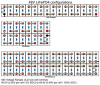
Here is one of my Layout Diagram for 48V battery packs.

Currenty, the most popular & efficient BMS' available come from JKBMS. There are 2 versions essentially,
1) has Active Balancing, Bluetooth APP RS485/RS232 but "Independent"
LINK TO JKBMS CO info: http://www.jkbms.net/products?category_id=1717811175032811521
2) Also has Active Balancing but also has Inverter Interconnection which also supports the Victron Protocol allowing for integration into the Victron Ecosystems.
LINK TO JKBMS CO info: http://www.jkbms.net/product?id=1733033589518364674

48V Basic Prismatic Configuration.jpg
 
With 33 cells in parallel the key is going to be making sure the bus bars and connections are all good with low resistance so current is distributed evenly among the cells. Although slight imbalances will self correct near the end of charge or discharge cycles.

The Orion Jr2 is a suitable BMS to monitor and protect the cells from out of spec conditions but you will need a higher current balancer based on the large capacity of the battery bank. Would recommend something like a 10A stand alone JK BMS or 15A NEEY active balancer.
Thank you for your response!

I was thinking of getting a solid copper bus bar, drilling holes where needed for the threaded posts and then drilling small holes on the threaded posts right above where a fully tightened nut would sit and placing a hitch pin through said hole. This would mechanically lock everything in place, thoughts?

Thank you for the current balancer advice, will add that to my list!
 
......and then drilling small holes on the threaded posts right above where a fully tightened nut would sit and placing a hitch pin through said hole. This would mechanically lock everything in place, thoughts?
If your threaded posts are stainless, drilling a hole precisely in them is going to be difficult. When I had that configuration, I used Nordlok washers and flange nuts to insure the nuts did not loosen. The larger surface area of the flange nuts also help keep the heavy bus bars flat to the surface of the battery terminal tops. Also, just before assembling each bus bar, I polished the terminal tops and bottom of the bus bar to eliminate any oxidation and immediately applied NoAlox or similar product to prevent oxide from forming on that interface.
 
First & Most Important rule in systems design & Planning is to Keep It Sweert & Simple !
The more complicated you make it the more problematic it can be.
For 48V System, use a 16S Configuration (Normal Default) which provides a working voltage range 48.0-54.5. LFP has a very flat voltage curve and this voltage range covers the voltage Range that delivers the specified Amp Hours of the cells.

If paralleling cells, this is only done with properly Matched & Batched cells otherwise paired cell imbalances *(they happen) will cause issues that are hard to resolve and waste a lot of time.. plus have potential to cause harms.

It is far better to build Multiple 48V/16S Battery Packs, and place them in Parallel. P{acks in Parallel within a Battery Bank will Share / Divide both Load & Charge while providing fall back protection... should any pack in the bank stop, the rest continue.

Here is a Guide I wrote a while back for Assembling an LFP Battery Pack - there is a lot of handy info in this PDF.
Luyuan Tech Basic Lifepo4 Guide V1.0A

Here is one of my Layout Diagram for 48V battery packs.

Currenty, the most popular & efficient BMS' available come from JKBMS. There are 2 versions essentially,
1) has Active Balancing, Bluetooth APP RS485/RS232 but "Independent"
LINK TO JKBMS CO info: http://www.jkbms.net/products?category_id=1717811175032811521
2) Also has Active Balancing but also has Inverter Interconnection which also supports the Victron Protocol allowing for integration into the Victron Ecosystems.
LINK TO JKBMS CO info: http://www.jkbms.net/product?id=1733033589518364674

View attachment 207884

Thank you for your response!

I would only be able to charge and discharge at a rate of ~12A per battery as my solar caps at 20 kW input and my inverters can only pull 20 kW output. As long as the are all top balanced for voltage, which will be done before it is assembled, the Ah rating will become less problematic whether they are defective and only have 67Ah of capacity or are perfectly fine and give 74Ah. All of the negative terminals will be bolted directly to a bus bar. The positive bus bar will run down the middle of the cell (from left to right across all 33 batteries, positive terminals above and negative terminals below said bus bar). Between the positive terminals and the bus bar will be 15A glow fuses. When a fuse is glowing, it means I need to check that specific cell. While the fuse could blow on my best batteries if I drain my system as low as it will go, I do not plan to go below 10% capacity or 7.4 Ah per battery. This gives me a lot of tolerance for the actual capacity of the cells. With that being said, if there is any problem with a single cell and it shorts, the fuse will blow protecting the rest of the system.

The only issue I have with 33 48V batteries is the need for 33 BMSs instead of 1. I am trying to do this as cheaply as possible by doing most of it DIY (Victron is a guilty pleasure). Does my fuse idea clear up your concerns or am I just creating more problems?

Thanks again, I appreciate the detailed response!
 
If your threaded posts are stainless, drilling a hole precisely in them is going to be difficult. When I had that configuration, I used Nordlok washers and flange nuts to insure the nuts did not loosen. The larger surface area of the flange nuts also help keep the heavy bus bars flat to the surface of the battery terminal tops. Also, just before assembling each bus bar, I polished the terminal tops and bottom of the bus bar to eliminate any oxidation and immediately applied NoAlox or similar product to prevent oxide from forming on that interface.
Thank you!

I will implement that on the negative bus bar however the positive bus bar will not be sitting directly on top of the terminals. I tried to describe how it would be setup in my most recent comment to Steve_S.

I will buy a bunch of the Nord Lock washers and flange nuts though, they've been added to the list!
 
I am looking to arrange my batteries in 16S33P. Basically I will have 16 rows of batteries.
That would be 33P16S and only require one BMS. I do agree with the other poster that the Orion does not have enough balancing current to keep that pack in balance. I used an Orion JR BMS for years on my 3P16S pack of LF280 cells and used a jK 2 Amp active balancer to assist. I turned off the balancing on the BMS and let the balancer do that function. The Orion does have a very acurate Coulomb Counter so the SOC output is very close if you ocassionally make sure it resets by charging to the top.
 
I tried to describe how it would be setup in my most recent comment to Steve_S.
I guess I need a picture to understand. I also dont understand the configuration, especially that all the negatives are in parallel?. It initially sounded like you had a 33P16S pack even though you described it at 16S33P.
 
I guess I need a picture to understand. I also dont understand the configuration, especially that all the negatives are in parallel?. It initially sounded like you had a 33P16S pack even though you described it at 16S33P.

That was my fault, 33P16S is correct.

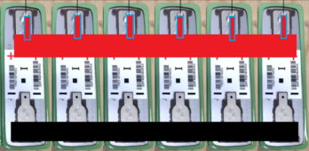
Black is the negative bus bar. Red is the positive bus bar. Red outlined in blue are the 15a fuses. This is only 6 however there would be 33 per row and 16 rows.
1712591635176.png
 
Did you purchase these cells already or can we still try to talk you out of it?
I am wondering the same thing. Is the cost of those cells so cheap it is worth all the work of assembling them? A quick Google search on those cells reveals one source is JAG35. I have been following Jehu since his VW conversion in 2014 and he is constantly evolving and I suspect these are surplus cells of unknown origin.
 
Did you purchase these cells already or can we still try to talk you out of it?
I am all ears. I am not dead set on these cells. I am also looking at 544x Calb CAM72 cells as well as 5x Nissan Leaf 153.6V 180Ah (96x 3.2V 90Ah cells from what I could read) packs.
 
I am all ears. I am not dead set on these cells. I am also looking at 544x Calb CAM72 cells as well as 5x Nissan Leaf 153.6V 180Ah (96x 3.2V 90Ah cells from what I could read) packs.
Do you have a predilection for specialty cell formats? Bus bars are not fun to make if you ask me. Why not just join the party with 280/304's? The water's warm.
 
Then one BMS should work. What is the cost per kWh compared with the 280-300 Ahr cells that have been averaging $80/kWh?
~$130.00 / kWh. This includes shipping, the cells, fuses and the 47 copper bus bars. I can break it down for just the cells but I do not have that info in front of me at the moment.
 
Do you have a predilection for specialty cell formats? Bus bars are not fun to make if you ask me. Why not just join the party with 280/304's? The water's warm.
Am I able to get 125 kWh for less than $16k including shipping, taxes, fuses and cables?
 
Last I checked you can get about 120kWh for $16k from 18650 or Ezeal for just the cells.
I did too many hours of research and came across the previously mentioned 3 cells. Shipping and taxes....etc 18650 cells would not be as cost effectively unless I scavenged for awhile and on top of that, the amount of them I would need for 125kWh...making that array would take many many man hours.
 
Back
Top