diy solar

diy solar

Wanptek DC Power Supply - FUSE Replacement

NCislander

Solar Enthusiast
Joined
Oct 18, 2019
Messages
322
Location
North Carolina Mountains
I am using a DC Power Supply (Wanptek KPS 100v/10amp) unit.
Fuse is located in the 120vac input plug assembly. Unit states to use a 250v rated fuse, no ampherage rating for replacement.
The fuse is blown, writing on its description Un-Readable.

Do any users out here have ANY Wanptek KPS DC Power Supply? One you could look at your fuse rating, what you have installed?

Wanptek documentation does not give fuse amp rating, only voltage (250v fuse)

-Thanks for any help.
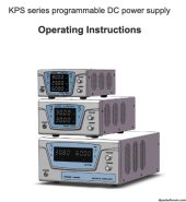
Wanptek KPS 100:10 Power Supply.jpg
 
This is a 1000w unit, so 1000w at 120v is 8,33 amps. The fuse probably was a 10 amp one. Maybe you should try to contact them at wanptek.com
 
I suspect it is a 12A fuse. Also suspect there are bigger problems. Put a 100W incandescent lamp in series with the power cord and short out the fuse with aluminum foil to test. If the lamp is bright and not dim, I wouldn't waste money on a fuse. Fuses have gotten very expensive. Hope this is under warrantee.
 
Not under any warranty (eBay purchase). Though it had functioned as advertised, was using it to Top Balance cells at 10 amps. I ran it non stop for almost 9 days. Hopefully the fuse replacement brings it back. Its actually been a handy power supply.
Variable voltage 0-100vdc & variable ampherage 0-10 amps.
I'll order replacement 8 amp/10 amp/12 amps fuses. Burned fuse was glass, 20mm length, 250v. unknown ampherage.

Unsure if I want to try the dim bulb/foil test.
 
If there is something wrong internally, and it sounds like there could be from doing a long term charge, replacing the fuse and plugging it in will do further damage to electronics. The dim bulb tester is a standard diagnostic procedure. Install the fuse and then test. All my power supplies were broken ones on ebay. I have to use a USB microscope to see a lot of the printing/stamping on electronics. The amp rating is there.
 
Not under any warranty (eBay purchase). Though it had functioned as advertised, was using it to Top Balance cells at 10 amps. I ran it non stop for almost 9 days. Hopefully the fuse replacement brings it back. Its actually been a handy power supply.
Variable voltage 0-100vdc & variable ampherage 0-10 amps.
I'll order replacement 8 amp/10 amp/12 amps fuses. Burned fuse was glass, 20mm length, 250v. unknown ampherage.

Unsure if I want to try the dim bulb/foil test.
Is very surprising, fuses have their amp rating engraved/stamped/printed somewhere allways. Are you sure that this one doesnt have any markings or very small engraved number in the metal ends?
 
If there is something wrong internally, and it sounds like there could be from doing a long term charge, replacing the fuse and plugging it in will do further damage to electronics. The dim bulb tester is a standard diagnostic procedure. Install the fuse and then test. All my power supplies were broken ones on ebay. I have to use a USB microscope to see a lot of the printing/stamping on electronics. The amp rating is there.
Ill look into testing with it. While awaiting ordered fuses.
 
Ill look into testing with it. While awaiting ordered fuses.
I sent a message to the fellas at wanptek.com for you, they have answered quite quickly. The fuse you need for the KPS10010 is 10 amps.

From wanptek:

5*20mm。10A

发自我的iPhone

> 在 2023年9月4日,02:58,
>
>
cleardot.gif
 
As a quick follow up. Amazingly, an email to: wanptek@126.com The Contact Us email contact, replied back within hours of my request for information.
20mm, 250v 10 amp fuse.
It was a long shot to email wanptek directly. Pleasant surprise.
I have a stigma, Chinese vendors not being very reachable. I was mistaken.
 
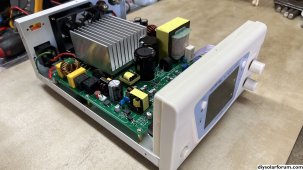
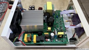
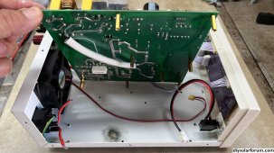
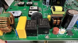
Follow up to this thread. The 5*20mm 10amp fuse did not correct the problem. Deeper issues on the power supply. Power Relays (2) just after the input power look burnt/heated on underside of the board. Not really knowing how to troubleshoot to component level, I'm going to try replacing obvious components as cost allows. A few dollars in parts and soldering replacements, hopefully something easy (Not normally)
It's a power supply worth repairing, if possible.
 
IMG_2161.jpg
IMG_2160.jpg
IMG_2162.jpg
IMG_2164.jpg

I ordered replacement (Black Square JQC-3FF) components to start. These are where the heat/flash/burn on the inside case.
Unsure what the yellow component is to the left.
 
I would have given you a handful of those. My guess is they may be still good. One is power on/off and other likely switches from 220 to 110V. That looks like a lightning strike from the mark on the case. Check the black square rectifier on the left for shorts pin to pin, there are four internal rectifiers, The yellow thing is a safety X type capacitor that is designed to fail safely and in many cases doesn't even function after a few years. The real concern is the two FET to the right. Check ohmage across the two outside pins These will typically fail in a short of less than 40 ohms. The other two are diodes. Their two outside pins are likely connected together, verify with looking at trace. The red can next to relay is a fuse which supplies control power. That goes to the small bridge rectifier, again look for shorts. Repairing that fuse will get it to light up. if not the chip to the right may be bad. That low voltage control supply is likely powered all the time.
 
I would have given you a handful of those. My guess is they may be still good. One is power on/off and other likely switches from 220 to 110V. That looks like a lightning strike from the mark on the case. Check the black square rectifier on the left for shorts pin to pin, there are four internal rectifiers, The yellow thing is a safety X type capacitor that is designed to fail safely and in many cases doesn't even function after a few years. The real concern is the two FET to the right. Check ohmage across the two outside pins These will typically fail in a short of less than 40 ohms. The other two are diodes. Their two outside pins are likely connected together, verify with looking at trace. The red can next to relay is a fuse which supplies control power. That goes to the small bridge rectifier, again look for shorts. Repairing that fuse will get it to light up. if not the chip to the right may be bad. That low voltage control supply is likely powered all the time.
It was not any lightening strike. I was attempting a charge on my DIY cells (10 Amps), the max the power supply can put out. I've used it earlier last month for as long as a week @10amps without issue. I'm assuming components on the board got maxxed out to failure (Pop!)
I was a few feet away when it popped.
 
That looked like a flashover. If you put a fuse in and it did nothing. Didn't blow the fuse. The problem in in the control power supply. You can put an AC cord tight on the small bridge rectifier on the AC pins and operate the displays if that fuse is blown. It is powered all the time the supply is plugged in That supply is just like your wall wart phone charger which operates on 100-240V AC. Pressing the on button only turns the power relay to the switching FET.

This is repairable without too much effort and becoming a parts replacer. I hate those guys. Do noy replace those relays yet. Simple diagnostics will lead you to the problem without a lot of test equipment. Back in the early 60's my first job was repairing transistorized electronic organs when I was 14. I was the only one who understood transistors. I spent more time in bars than when I was legal. Always found repairs were relaxing. I just bought a Renogy boost charge controller to fix. Will has one of these for his golf cart. I don't even own a golf cart and don't know what I will do once it is fixed. It will just be fun. You will have a lot of satisfaction once you fix this. Anybody need one of these? Your repair doesn't sound like a big problem.
Input power cord fuse (10 amps) still blows upon turn on. No display, just Pop!
 
Back
Top