diy solar

diy solar

Interesting problem over paneling with parallel strings

fourtytwo

New Member
Joined
Jul 13, 2021
Messages
72
Location
UK, Nlincs
Hello I have a ~1Kw inverter with two ~1Kw PV strings in parallel pointing in slightly different directions.
As expected MPPT handled the combination with no problem even though there was a voltage difference.
However what I was not expecting is that when up against the inverter power limit in full sun MPPT finds many different voltage/current combinations to provide 1Kw and unfortunately was tending to lean towards lower voltages and higher currents. e.g. 120V@8.3A =1Kw but so does 80V@12.5A increasing ohmic losses and reducing efficiency.

What I chose to do was to implement thermal current limiting by averaging input current over a minute and forcing mppt to increase voltage a step if the limit were exceed (increasing voltage will reduce current) until such time as the average current subsides.

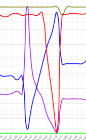
Another tactic was to reverse the direction of the periodic voltage scan that hunts for the true peak power, it used to scan from the highest to the lowest voltage and hence report the peak with the lowest voltage, having discovered this is sub-optimal it now scans from the lowest to the highest voltage reporting the highest voltage that produces peak power. When the inverter is over paneled in this way the peak power corresponds to the maximum inverter power and under full sun is a plateau rather than a peak.

In the plot blue is volts, violet is amps & red is watts (ignore gold & green). This clearly shows the plateau as watts are maintained at maximum for a wide range of voltages.
low-high_scan.png
 
This is exactly what I've wondered about with overpaneling. Bad power points.

What do you think about just picking one good enough fixed voltage? I mean I can tell you've obviously come up with this more intelligent solution but what's your impression of the viability of one fixed voltage for heavily overpanelled systems?
 
How do you get such granular control over your MPPT?
Well there are actually two loops, an inner PID loop that controls voltage, that is it continuously adjusts the PWM to maintain a set PV voltage and then there is the outer MPPT loop that runs much slower and determines the setpoint voltage for the PIV loop. In the case of the periodic scan MPPT is switched off & replaced by the scanner that sets the setpoint voltage for the PIV loop instead.

The scanner has to run fairly slowly to ensure the PV input capacitor can charge/discharge between steps particularly at low powers so that the power measurement at each step is reasonably accurate.
 
Last edited:
This is exactly what I've wondered about with overpaneling. Bad power points.

What do you think about just picking one good enough fixed voltage? I mean I can tell you've obviously come up with this more intelligent solution but what's your impression of the viability of one fixed voltage for heavily overpanelled systems?
It all depends on weather your array suffers shading (as mine do) and large variations in temperature (most do), both cause vmpp to shift around in voltage at times quite dramatically, I can for example be running on only one of four panels(others being shaded) so vmpp is only one quarter of normal.

Of course the more over paneled parallel strings you have the less the shading is an issue, I have certainly been able to maintain maximum power over a wider range of hours than I did before. That tends to imply the need for extreme voltage agility decreases but I am to chicken to try without lols (let me know how you get along).

If you were going to fix something then having a hard upper current limit might be ok as it allows the voltage to remain agile to combat shading but protects the inverter from damage. I would imagine that is what some commercial products do.
 
Last edited:
However what I was not expecting is that when up against the inverter power limit in full sun MPPT finds many different voltage/current combinations to provide 1Kw and unfortunately was tending to lean towards lower voltages and higher currents. e.g. 120V@8.3A =1Kw but so does 80V@12.5A increasing ohmic losses and reducing efficiency.

Does it really matter (other than heating up the wire a little more) if you are still getting 1kw out of the MPPT?
 
It all depends on weather your array suffers shading (as mine do) and large variations in temperature (most do), both cause vmpp to shift around in voltage at times quite dramatically, I can for example be running on only one of four panels(others being shaded) so vmpp is only one quarter of normal.

Of course the more over paneled parallel strings you have the less the shading is an issue, I have certainly been able to maintain maximum power over a wider range of hours than I did before. That tends to imply the need for extreme voltage agility decreases but I am to chicken to try without lols (let me know how you get along).

If you were going to fix something then having a hard upper current limit might be ok as it allows the voltage to remain agile to combat shading but protects the inverter from damage. I would imagine that is what some commercial products do.
Yeah my CC (Schneider MPPT 100 600) only has two MPPT modes, free floating power point and fixed target voltage. I have not experimented to find out of target voltage mode means it searches anywhere below and up to the target, or locks on the target only.

I have a west facing array now, with some shading before 11am that I didn't notice when I was building it, from a power pole 30 ft away. This is nbd now because it's not in my main production curve which is 11am-7pm.

I am considering adding an identical array south or southwest paralleled to the due west array.

I am considering using fixed voltage because it might allow me to save on running more wire, if I can get the MPPT to never suck higher amperage power points. Then I can fuse the combined string at the array to protect the long run of wire to the CC. I also like that this would actually allow the array to blow the fuse on a short in the long run or at the CC. If any short ever occurred there during high production.
 
Does it really matter (other than heating up the wire a little more) if you are still getting 1kw out of the MPPT?
Longevity of the inverter and panels! Ohmic losses (heat) increase at the square of current so if the opportunity arises to run at 10A vs 15A I will take it. Peak to average ratio is also important in the PWM as it affects transformer and inductor dissipation and so running at different PV current vs voltage points has an effect here too.
 
I've just tried a target voltage. It was running at 395v/240w on this mornings obscure angle, cold panels, backside bifacial illumination.

Setting target voltage to 330v resulted in 215w output.

At this moment, that's an acceptable compromise. I would give up those 25w for a target voltage. But this doesn't test the opposite scenario of target voltage above the MPP.

If I set it to 500v target I see that it only goes up to around 415v and just runs completely out of juice. I don't think this is a good time to test higher than MPP target voltages, since they're above the open circuit voltage right now. I'm gonna call this inconclusive about whether target mode still looks for lower than target voltage power points, it may also just be that the MPPT was trying it's best to get to target but the panels couldn't do it.
 
Yeah my CC (Schneider MPPT 100 600) only has two MPPT modes, free floating power point and fixed target voltage. I have not experimented to find out of target voltage mode means it searches anywhere below and up to the target, or locks on the target only.

I have a west facing array now, with some shading before 11am that I didn't notice when I was building it, from a power pole 30 ft away. This is nbd now because it's not in my main production curve which is 11am-7pm.

I am considering adding an identical array south or southwest paralleled to the due west array.

I am considering using fixed voltage because it might allow me to save on running more wire, if I can get the MPPT to never suck higher amperage power points. Then I can fuse the combined string at the array to protect the long run of wire to the CC. I also like that this would actually allow the array to blow the fuse on a short in the long run or at the CC. If any short ever occurred there during high production.
I found the manual so impenetrable I could not find any reference to those settings however fixing the array voltage is not going to limit the available current! Are you saying you would use a wire and hence a fuse below Isc for those panels ?
 
I've just tried a target voltage. It was running at 395v/240w on this mornings obscure angle, cold panels, backside bifacial illumination.

Setting target voltage to 330v resulted in 215w output.

At this moment, that's an acceptable compromise. I would give up those 25w for a target voltage. But this doesn't test the opposite scenario of target voltage above the MPP.

If I set it to 500v target I see that it only goes up to around 415v and just runs completely out of juice. I don't think this is a good time to test higher than MPP target voltages, since they're above the open circuit voltage right now. I'm gonna call this inconclusive about whether target mode still looks for lower than target voltage power points, it may also just be that the MPPT was trying it's best to get to target but the panels couldn't do it.
I think this is confusing MPPT & "target voltages" maybe ? Surely this "target voltage" is constant voltage and is a mode that avoids the use of any MPPT algorithm at all.
 
I found the manual so impenetrable I could not find any reference to those settings however fixing the array voltage is not going to limit the available current! Are you saying you would use a wire and hence a fuse below Isc for those panels ?
Oh. I forgot to describe this part: The CC is limited to 100amp output, at 55v = 5500w, 5500w / 330v = 16.66A, for 20A fusing.

I am relying on the CC's output current limit to limit the input current at a fixed voltage. Yes wire and fuse below ISC.
 
I think this is confusing MPPT & "target voltages" maybe ? Surely this "target voltage" is constant voltage and is a mode that avoids the use of any MPPT algorithm at all.
Capture.PNG
These are the two settings. The latter reference range can only be adjusted and maintained at it's setting by disabling the former toggle.

So yes, it does seem like it should not be tracking lower voltage power points, but I'm still worried it can find them and blow the fuse. I don't mean to derail your interesting thread with my own quibbles with this Schneider CC though.
 
Oh. I forgot to describe this part: The CC is limited to 100amp output, at 55v = 5500w, 5500w / 330v = 16.66A, for 20A fusing.

I am relying on the CC's output current limit to limit the input current at a fixed voltage.
IMOP that's quite likely a dangerous assumption, after all, it want's 5500W+losses from the input and it will use whatever combination of volts and amps it fancies to obtain it!
 
View attachment 213623
These are the two settings. The latter reference range can only be adjusted and maintained at it's setting by disabling the former toggle.

So yes, it does seem like it should not be tracking lower voltage power points, but I'm still worried it can find them and blow the fuse. I don't mean to derail your interesting thread with my own quibbles with this Schneider CC though.
Ahh very interesting, do you know what Voc is for your array (measure with breaker open) then set the target voltage maybe 20V below Voc and make sure it sticks there as it's only operating point.

I think your comments with a commercial product and similar parallel strings very relevant to this thread :)
 
IMOP that's quite likely a dangerous assumption, after all, it want's 5500W+losses from the input and it will use whatever combination of volts and amps it fancies to obtain it!
Well I wouldn't trust the CC's limiting for safety, but I do trust a quality name brand fuse placed upstream of the constrained wire ampacity. If the fuse blew then yes it would be time to buy and pull more wire. To put it better: I am relying on the CC's output limit only to not blow the fuse, and I would be relying on the fuse to protect the wire.
 
Well I wouldn't trust the CC's limiting for safety, but I do trust a quality name brand fuse placed upstream of the constrained wire ampacity. If the fuse blew then yes it would be time to buy and pull more wire. To put it better: I am relying on the CC's output limit only to not blow the fuse, and I would be relying on the fuse to protect the wire.
Well by the sounds of it you really are going to rely on that fuse for fire protection so I hope you take into account the mounting and cooling of that cable in calculating it's hoped for ampacity!
 
Ahh very interesting, do you know what Voc is for your array (measure with breaker open) then set the target voltage maybe 20V below Voc and make sure it sticks there as it's only operating point.

I think your comments with a commercial product and similar parallel strings very relevant to this thread :)
I'll try some more later today in good production. It's 448v VOC by the spec sheet. MPPT usually finds 330-350v at peak output. I'll try 380 or 400 fixed then and see it if it stays there or still wants to find the 330-350v.
 
I'll try some more later today in good production. It's 448v VOC by the spec sheet. MPPT usually finds 330-350v at peak output. I'll try 380 or 400 fixed then and see it if it stays there or still wants to find the 330-350v.
Done this test now. It was running at 350v/700w and I set it to 380v MPPT off, and it did stick at 380v/600w.

From these tests I conclude that if I set it to say 330v, then it will really stick near 330v even in the presence of either a higher or lower voltage real MPP. With the exception that in low illumination states where the array's VOC is say 220v, it can and will only get 220v there, but in such a state the available current output is going to be low to near 0 anyway, so it's not likely that these edge cases would be fuse blowing events.
 
View attachment 213623
These are the two settings. The latter reference range can only be adjusted and maintained at it's setting by disabling the former toggle.

So yes, it does seem like it should not be tracking lower voltage power points, but I'm still worried it can find them and blow the fuse. I don't mean to derail your interesting thread with my own quibbles with this Schneider CC though.
So what inverter is this?
 
Back
Top