diy solar

diy solar

Stalling Issue on turbine

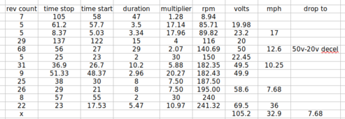
yes, did that early on, pretty similar to my later results but only had a DMM then, had to try to estimate the rpm by counting the times the blue stripe passed me while I was looking at the clock. Not very accurate. The graph used RPM calculated from movies taken of it while monitoring dmm and windspeed indicator, frame by frame count of the revs. Accurate, but not all readings available on every instance. Thats why the mph on the chart has a sag while the rpms are increasing, no reading of windspeed at that time.
 
tonite had a pretty stiff breeze, enough to at least start the turbine, but I noticed that it didnt even move. I went out and tried to move the blades with a long pole, they barely moved at all, very stiff. After almost turning them half a revolution, a sparrow crawled out through a small hole in the front and it began to turn much easier. I disconnected the power for the night, hoping it would spin up and maybe keep them out long enough for me put more screen around it tomorrow.
 
Is the blue line on the graph with no load (open circuit) and the tan line under load?
 
Blue is rpm under no load, tan line is voltage at that rpm, no load
 
The chart had windspeeds up to 30 mph when I was testing. It will start unloaded in 7 mph. Only way I see is bigger swept area (more and larger blades, I could go to 80"), or taller tower (working on that). I had no problem with the old car batteries, but these new AGM's seem different, thats why I added a solar component, to keep the batteries as full as possible.
 
I just completed a jumper cable with MC 4 connectors and a ceramic light bulb outlet, and found a working 40 watt appliance bulb, will be trying the lightbulb trick as soon as the wind cooperates, meanwhile I will scrounge a few more different wattage bulbs. At least that option is cheaper than new blades. Didnt see an old boot yet, but it is probably there. Quite the pile of chicken feathers and straw came out. Didnt find any bird in there when I came home today at least, maybe the screen is covering enough. I also unpinned the rotation so it can move with the wind anywhere from NNW to SSW.
 
I just completed a jumper cable with MC 4 connectors and a ceramic light bulb outlet, and found a working 40 watt appliance bulb, will be trying the lightbulb trick as soon as the wind cooperates, meanwhile I will scrounge a few more different wattage bulbs. At least that option is cheaper than new blades. Didnt see an old boot yet, but it is probably there. Quite the pile of chicken feathers and straw came out. Didnt find any bird in there when I came home today at least, maybe the screen is covering enough. I also unpinned the rotation so it can move with the wind anywhere from NNW to SSW.
I am curious to know the results. It's hard to believe the agm batteries made that much difference.
 
I just completed a jumper cable with MC 4 connectors and a ceramic light bulb outlet, and found a working 40 watt appliance bulb, will be trying the lightbulb trick as soon as the wind cooperates, meanwhile I will scrounge a few more different wattage bulbs. At least that option is cheaper than new blades. Didnt see an old boot yet, but it is probably there. Quite the pile of chicken feathers and straw came out. Didnt find any bird in there when I came home today at least, maybe the screen is covering enough. I also unpinned the rotation so it can move with the wind anywhere from NNW to SSW.
Thank's for the update. Let me know if I am reading your graph correctly. The left vertical column is no load rotor rpm. Top horizontal row is no load DC output voltage. Referring to the blue polynomial line, I interpret the DC output to be approximately 2.5 volts @ 90 rpm and 10.3 volts @ 210 rpm. If that is correct, I am still confused what the brown line represents. Using the same logic, I interpret the brown polynomial line to indicate 10 volts at 45 rpm. It looks like the MPH line is sharing the numbers used for rotor rpm. If that is the case, are you not achieving 12 volts no load until a 30 mph wind?
 
The upper axis line is simply the test number, or reading number. Not all readings obtained all the data, you can see the inflection points if you draw lines down vertically from the test number. For instance the gray line (wind speed) only captured results at test 3, 10,12, and 13. I graphed all results against the left axis numbers.

As a followup to the bulb test, I went out this morning in the dark and hooked the jumper line into the positive turbine feed with the bulb "on". Then I got to work and was thinking will this drain my batteries? The turbine lines are directly hooked to the batteries. The turbine is not spinning at the moment (no wind before dawn), today is not supposed to be much wind, maybe 5 mph from the north, so I dont expect it to be running all day, so nothing being generated at the generator, so I assume no current flow to drain anything. Be a problem if I get home to dead batteries! I am thinking not an issue though.

Raw data attached for reference -
 

Attachments

  • Screenshot from 2024-02-07 08-36-55.png
    Screenshot from 2024-02-07 08-36-55.png
    42.8 KB · Views: 2
Ok, now I get it. Nice work on the graph. Your batteries are fine. The diodes in the generator keep that from happening.
 
yup, confirmed that the batteries were ok when I got home. No wind today, but I did scrounge up a 65 watt halogen bulb and an old but working 100 watt bulb, to add to my 40w appliance bulb. Not likely I have anything smaller, and getting them is near impossible now. So waiting for a decent wind to run some tests.
Graph was done very early on, as soon as I had rewired the stator. Tests were done exactly where it is now, so no new variables introduced, except for the batteries, I had an old car battery in it last year. I didnt decog this one as these early tests showed no issues starting up, but cogging is barely noticeable when spun by hand.
 
When you try this, do you have a meter to put in series with the battery? With a 120 volt bulb in series, I would not expect much current flow at all.
Just a wild guess, somewhere between 100 milliamps and maybe 1 amp. What I hope happens is the rotor turns and you get some current flow.
After that, you can start looking at something along the lines of what High Desert recommended, a cube relay with maybe a voltage divider circuit. Below is a solid state relay I used to fix a similar problem. I have solar panels directly hooked to a DC motor driving an AC compressor. The motor was bogging partially because it was starting at too low of a sun level. I put a small 5 watt/12 Volt panel across the 3-32 VDC input with a variable resistor in series to adjust the on/off based on sun intensity. Works very well. I found it on Amazon.
 

Attachments

  • IMG_7084.JPG
    IMG_7084.JPG
    170.5 KB · Views: 4
4X3 Star pattern, 36 pole F&P motor, 3 phase into rectifier at the motor, 2 wire DC out. Enters the building and goes to dist block which feeds the batteries and the dumpload on the controller. Wind controller on the left side of pic (w /voltmeters) is run directly from batteries. Wind controller will activate dumpload at 14.8v. Solar controller is a separate system on the right side.
Designed to give 50v at 10 mph wind at 180 rpm, startup at 7 mph (unloaded).
How many ohms and what is the wattage rating of the blue load dump resistor on the right in your photo?
 
There are two 300w dump loads, the second one can be switched out of circuit in case its too much. Dont have Ohm info available ATM. (at work)
As for the voltmeter, yes, I have one to put in series but having tried that before I just get battery voltage (in the pic it sits right above the wind controller), unless of course you mean inserting it between the bulb and the turbine? Or that with the bulb in the circuit I would get a different reading than battery voltage (as it is trying to flow through the bulb?) Ahh, I see, in series on the positive feed, got it. Sorry, had a stroke a couple of months ago and my brain is moving very slowly. Sorry for the confusion. Yes, I think I can do that. Again, just waiting for some wind now.
 
The SSR looks interseting but I know the turbine will put out more than 60v. something like this maybe better? 250VDC at 40 amps? I know its a bit overkill, but since this imported stuff has a high failure rate, staying away from full scale operation might make it last longer?
What would I trigger the relay with? I could parallel the turbine feed, but that would kick it in too low (3v?) The minimum voltage doesnt seem to be adjustable. I could use a solar panel (I have some 100w panels around) that would kick in around 20v or so, but only during the day.
An old school centrifugal rev limiter would work well, very steampunk.
 
OK, so I could use this to trigger the SSR as it would supply a fraction of the PMA feed rather than the full amount. I need the resistance values to determine where the cut in voltage will be. A variable resistor is a good idea. So I split off a parallel feed to this reducer, convert it to a lower voltage that will trigger the relay to close at a higher voltage than I am getting now. I havent played with electronics since the 70's, but I was decent back then. Thanks for all the help in this forum, I think I can get this up and spinning away again. So next step is to determine resistance values, which I assume is what the lightbulb will help me do.
 
OK, so I could use this to trigger the SSR as it would supply a fraction of the PMA feed rather than the full amount. I need the resistance values to determine where the cut in voltage will be. A variable resistor is a good idea. So I split off a parallel feed to this reducer, convert it to a lower voltage that will trigger the relay to close at a higher voltage than I am getting now. I havent played with electronics since the 70's, but I was decent back then. Thanks for all the help in this forum, I think I can get this up and spinning away again. So next step is to determine resistance values, which I assume is what the lightbulb will help me do.
Yessir. Exactly.
 
Back
Top