


I am converting my motorhome coach from using FLA batteries to LiFePo4 and wanted to share my final design/build. I've read hundreds of posts on the need for and reasons to compress the cells and have come down on the side of providing light compression.
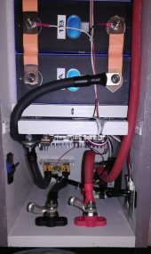
My 560Ah EVE LF280K 2P4S battery bank will be mounted in an outside storage compartment by my two 40A solar controller/chargers and within six feet of a 75A converter/charger and the original FLA distribution panel.
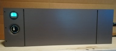
I was looking for a design that minimized the footprint of the bank as it will be displacing much-needed storage space for all my RVing crap. All the designs I've seen use a threaded-rod compression design but I wanted eliminate the rods as they added extra width to the sides of the bank.
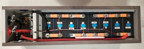
I came up with a box design that uses a pressure plate instead of rods. The pressure plate is pushed against the cells using five set screws and t-nuts mounted into the fixed board (BMS is mounted on this board). The set screws hit metal washers on pressure plate to keep from digging into the wood. Just like a rod design, the set screw/pressure plate design can be adjusted to provide whatever compression you want.
There are silicon sheets between the cells (and at each end), mainly to help with cell movement in this mobile application. I've also placed 1/8" foam underneath and along the sides of the cells to help with shock absorption. These might not help but they make me feel better.
Hopefully this alternate design will give fellow DIYers an idea or two.
My 560Ah EVE LF280K 2P4S battery bank will be mounted in an outside storage compartment by my two 40A solar controller/chargers and within six feet of a 75A converter/charger and the original FLA distribution panel.
I was looking for a design that minimized the footprint of the bank as it will be displacing much-needed storage space for all my RVing crap. All the designs I've seen use a threaded-rod compression design but I wanted eliminate the rods as they added extra width to the sides of the bank.
I came up with a box design that uses a pressure plate instead of rods. The pressure plate is pushed against the cells using five set screws and t-nuts mounted into the fixed board (BMS is mounted on this board). The set screws hit metal washers on pressure plate to keep from digging into the wood. Just like a rod design, the set screw/pressure plate design can be adjusted to provide whatever compression you want.
There are silicon sheets between the cells (and at each end), mainly to help with cell movement in this mobile application. I've also placed 1/8" foam underneath and along the sides of the cells to help with shock absorption. These might not help but they make me feel better.
Hopefully this alternate design will give fellow DIYers an idea or two.
Attachments
-
 1 - 12v 2P4S Front.jpg135 KB · Views: 165
 -
 2 - 12v 2P4S Front 2.jpg70.2 KB · Views: 188
 -
 3 - 12v 2P4S Overhead.jpg185.3 KB · Views: 201
 -
 4 - 12v 2P4S Components Compartment.jpg129.9 KB · Views: 193
 -
 5 - 12v 2P4S BMS Attachment.jpg89.8 KB · Views: 173
 -
 6 - 12v 2P4S Compression Plate.jpg90 KB · Views: 164