EG4 6000xp talking to 3 EG4 LL V2 batteries using CAN port. I liked being able to see each battery like I had with just Solar Assistant connected to the batteries. Is there anway to setup the 6000xp to get BMS info from the batteries as well as all me to get more detailed info from SA about the individual batteries?


You are using an out of date browser. It may not display this or other websites correctly.
You should upgrade or use an alternative browser.
You should upgrade or use an alternative browser.
Anyway to get Solar Assistant Battery info when EG4 LL in BMS mode?
- Thread starter crzykidd
- Start date
fmeili1
Solar Enthusiast
It's not possible in the current version of SA (see SA docu: Connecting the EG4 GYLL battery), the first battery has to be at address #2. But to be able to do closed loop communication between EG4 inverters and EG4 batteries, the first battery has to be set to address #1 (described in 5.3 and 5.4 in the EG4-LL V2 document) and this is not supported by SA.
I've already asked SA to get this supported in the future, but I don't know of any plans nor time frame so far.
Just my 2 cents:
I have come to the conclusion that the value of closed loop AIO to BMS-Battery communication is overrated and not really important. It's not worth the effort (e.g. possible protocol incompatibilities, required firmware updates for AIO's and/or batteries, additional wiring, etc.)
The obvious advantages of possible SOC settings in the AIO at first glance (e.g. settings for "back to grid" and "back to battery") are not really helpful if the SOC gets inaccurate over the time and this happens with LFP batteries when they are not charged more or less always to 100% (to let the BMS re-calibrate it's SOC value). I know, that because of the flat voltage chart of LFP batteries, that for the middle SOC range, voltage is not a good indicator for predicting the SOC. But for using it to set the "back to grid" and "back to battery" settings, voltage is accurate enough because it's at the beginning of the voltage/SOC chart where the voltage slope it higher in this range.
The other benefits e.g. reducing the charging voltage of the AIO because the BMS asked the AIO to do so is not really helpful if you'll have more than one battery in parallel - which is mostly the case.
You also loose transparency because the selected values in the AIO may be dynamically changed because BMS asked for them and you have no way to "see" which values are active at the moment.
Correct voltage settings for the charging voltages and max. charging current are sufficient for a reliable setup. For me it's more important to have all the detailed battery values in SA compared to have a closed loop AIO/BMS communication.
I know it's been a few months since there's been activity on this thread, but for anyone still interested I actually got this exact scenario working with the current release (2023-08-16) version of Solar Assistant on my EG4 LL-S batteries. Initially, I saw the exact same behaviour that @crzykidd reported above, and read the same comment on SA's help page that @fmeili1 refers to. Still, I thought I'd get out my RJ45 crimpers, open up BMSTools and see what exactly is being sent on each of the 2 RS485 busses.
The SA team is correct, by default if one of the batteries set to ID1 (i.e. master mode), the battery changes the protocol used and neither BMSTools nor SA can interpret it. You can increment all your battery IDs by 1 as suggested by the SA team, but then your battery bus has no master and your inverter won't detect anything. You can also see that your batteries aren't communicating with each other by the lack any activity on the batt comm ports' amber LEDs.
However, if you connect your 6000XP to the master battery via CAN bus on pins 4/5, and you connect Solar Assistant to the RS485 port via pins 1/2, AND you reconfigure all of your batteries to use the Schneider protocol on their RS485 ports instead of the default EG4 protocol, you can actually have the best of both worlds. I now have my inverter detecting and properly monitoring SOC, capacity, etc via CAN with by battery IDs starting at 1, and SA monitoring each individual pack via RS485.
Cheers,
-A
wildbillpdx
Solar Enthusiast
I had a similar issue with my 6000ex...but I added the EG4 communication hub between the inverter and the batteries (LifePower4). I have the batteries configured as IDs 1 to 4 and the SA usb cable plugged into the last battery. I now have BMS communication between the batteries and inverter plus details in SA.I know it's been a few months since there's been activity on this thread, but for anyone still interested I actually got this exact scenario working with the current release (2023-08-16) version of Solar Assistant on my EG4 LL-S batteries. Initially, I saw the exact same behaviour that @crzykidd reported above, and read the same comment on SA's help page that @fmeili1 refers to. Still, I thought I'd get out my RJ45 crimpers, open up BMSTools and see what exactly is being sent on each of the 2 RS485 busses.
The SA team is correct, by default if one of the batteries set to ID1 (i.e. master mode), the battery changes the protocol used and neither BMSTools nor SA can interpret it. You can increment all your battery IDs by 1 as suggested by the SA team, but then your battery bus has no master and your inverter won't detect anything. You can also see that your batteries aren't communicating with each other by the lack any activity on the batt comm ports' amber LEDs.
However, if you connect your 6000XP to the master battery via CAN bus on pins 4/5, and you connect Solar Assistant to the RS485 port via pins 1/2, AND you reconfigure all of your batteries to use the Schneider protocol on their RS485 ports instead of the default EG4 protocol, you can actually have the best of both worlds. I now have my inverter detecting and properly monitoring SOC, capacity, etc via CAN with by battery IDs starting at 1, and SA monitoring each individual pack via RS485.
Cheers,
-A

Quankl
New Member
- Joined
- Apr 10, 2022
- Messages
- 140
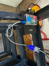
I had a similar issue with my 6000ex...but I added the EG4 communication hub between the inverter and the batteries (LifePower4). I have the batteries configured as IDs 1 to 4 and the SA usb cable plugged into the last battery. I now have BMS communication between the batteries and inverter plus details in SA.
View attachment 201702
Which type cable are you using from last battery to SA? And which protocol in Solar assistant. The normal black USB to RJ45?
Also is your inverter connected to SA as well and with which cable? USB Serial to RJ45 or Micro USB or not at all?
And confirm ID1, 2, 3 and 4. In terms of dip switch Up/down combination please for me.
Last edited:
wildbillpdx
Solar Enthusiast
I'm using the USB to RJ45 cable that comes with batteries connected to the PI running SA. Also using the inverter cable that came with the inverter to connect to the 6000ex (usb->serial->rj45). SA is running USB Narada RS485 to the batteries and, yes, IDs are 1, 2, 3 and 4.Which type cable are you using from last battery to SA? And which protocol in Solar assistant. The normal black USB to RJ45?
Also is your inverter connected to SA as well and with which cable? USB Serial to RJ45 or Micro USB or not at all?
And confirm ID1, 2, 3 and 4. In terms of dip switch Up/down combination please for me.
wildbillpdx
Solar Enthusiast
LIfePower4 or LL? Could be they operate differently when connected to the hub. I saw the post regarding the protocol change for the LL batteries and it doesn't mention the LifePower4 model specifically.I don't get the solar assistant to pick up the batteries in the last port using Narada RS485.
wildbillpdx
Solar Enthusiast
Yea lifepower 4. Same solar assistant version as you as well.

Quankl
New Member
- Joined
- Apr 10, 2022
- Messages
- 140
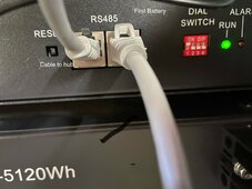
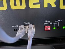
See attached.


Same cables as you have. Very strange. "Invalid data received" not "no response". So it's getting data just not correct?
Top cable is inverter to Battery.
Bottom black on is battery to SA. This used to work for me a while back. Then stopped.
wildbillpdx
Solar Enthusiast
Updated battery firmware? I updated all mine to the latest recently. Looks like maybe an incorrect baud rate. Can you communicate with the batteries using the BMS test software?
Last edited:
Quankl
New Member
- Joined
- Apr 10, 2022
- Messages
- 140
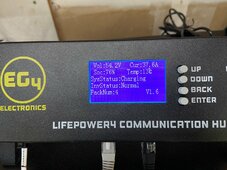
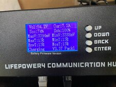
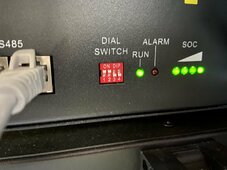
Latest firmware. I just check BMS tools. Batteries were in over voltage alarm and protect mode. But with no flashing red light and I'm using EG4 mode.
Can you share your battery setting on inverter with me? I thought eg4 was best but clearly not.
Can you share your battery setting on inverter with me? I thought eg4 was best but clearly not.
wildbillpdx
Solar Enthusiast
I’m using EG4 but I’ve got a cable running from the inverter to the com hub. I’ll get some photos in a few minutes.
Quankl
New Member
- Joined
- Apr 10, 2022
- Messages
- 140
Same. But eg4 mode somehow sent the battery into Overvolt mode.. idk. It's issue after issue with this on my end.I’m using EG4 but I’ve got a cable running from the inverter to the com hub. I’ll get some photos in a few minutes.
Quankl
New Member
- Joined
- Apr 10, 2022
- Messages
- 140
I put it in user. EG4 mode is pushing the batteries up to 57.6V and triggering the over protection... It's constantly pushing 5amps into each battery even at 100%
Why would they even do that when battery protection parameters start warning at 3.55 and protect at 3.6 per cell. 57.6 is 3.6v if it's 16 inside.
I'm actually on v3.32 for the battery. Will check through the changelog and see what's different
Why would they even do that when battery protection parameters start warning at 3.55 and protect at 3.6 per cell. 57.6 is 3.6v if it's 16 inside.
I'm actually on v3.32 for the battery. Will check through the changelog and see what's different
Last edited:
wildbillpdx
Solar Enthusiast
wildbillpdx
Solar Enthusiast
If you’re using the hub, first battery needs to be ID 1. There are also some charge settings on the hub, I think.Same. But eg4 mode somehow sent the battery into Overvolt mode.. idk. It's issue after issue with this on my end.
Attachments
wildbillpdx
Solar Enthusiast
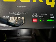
From your pictures batteries are ID 0 and 1, not 1 and 2. The hub needs the first battery at ID1. You said you are using the hub...are you actually connecting directly from the inverter to the batteries? If so, then ID 0 would be the first to allow closed loop communication between the inverter and batteries.No same exact setup as yours. Just I have the normal Lifepower 4 batteries without LCD. And Pi Zero 2w. I set as user and will test. I try not to update firmwares unless it's critical. Things always go wrong on my end.
Similar threads
- Replies
- 13
- Views
- 575
- Replies
- 0
- Views
- 149
- Replies
- 5
- Views
- 287
- Replies
- 2
- Views
- 278