With my setup (3x 100ah batteries) in 12v configuration and the 2000 watt inverter, what size fuse would you put on each battery between the bus bar? And what size wire would you use from the batteries to the bus bar?Putting the fuse at the bus bar end avoids this. Ideally you would fuse both ends of the battery wires, but most people don't and depend on the BMS to cut the current.


You are using an out of date browser. It may not display this or other websites correctly.
You should upgrade or use an alternative browser.
You should upgrade or use an alternative browser.
Swapping out
- Thread starter execv
- Start date
robbob2112
Doing more research, mosty harmless
With my setup (3x 100ah batteries) in 12v configuration and the 2000 watt inverter, what size fuse would you put on each battery between the bus bar? And what size wire would you use from the batteries to the bus bar?
My opinion -
Each BMS is 100amps max (but can spike higher momentarily, we plan on expected)
This from the windy nation welding wire chart - #6 will do the job with 115amps, but I would do #4 just for extra headroom at 150amps. Note this is a lot smaller than the 2/0 you originally listed because it is welding wire verse.

2 Gauge Pure Copper Ultra Flexible Welding & Battery Cable
WindyNation's Power-Flex welding and battery cable is a highly flexible industrial-grade electrical cable. A high strand cable count combined with a soft, pliable EPDM insulation results in a flexible cable every time. Our cable is resistant to tears, cuts, abrasion, water moisture, and...
www.windynation.com

Fuses on battery post and bus bar end of battery wire - both 150amp - Type is MRBF.
If you only put a fuse at one end of the battery cable put it at the bus bar end. In the event of a short across the posts realize you are depending on the battery BMS to act as a fuse and it could just as easy be a short instead of an open. If you fuse at the post and at the bus bar end you are covered for all eventualities.
For the inverter - you are running 2000watts/12.8v = 156amps - I would use #2 wire for this.
You can upsize if you ever think you want to run 3000w in future = 234amps = 1/0 wire.
Note - I skip 1 awg because it isn't a standard size of welding/battery wire. If you move to a THHN or other wire type that is a different ampacity chart.
For the fuse I would use a 200amp class T fuse as close to the bus bar as you can get.
For all fuses - cheaper isn't better - many people recommend blue sea systems, but they are just releabled Eaton, Bussman, or littlefuse with a higher price -So order from someplace like powerex
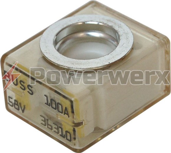
EATON's Bussman CBBF/MRBF Battery Terminal Series Fuses 50A to 300A
Requires the use of terminal fuse blocks CBBF-MBC, BS5191, BS2151, BS5194 or BS5196. Provides high current protection in tight space locations. Ignition protected. 58V DC maximum voltage.
On all cable ends use rubber boots to cover the bolt heads. The bus bars should be the type with a cover over it or you need to do something to prevent a short between them and everything else.
Big note here - if you don't have a good hydraulic crimper (temco or other quality brand, NOT the $40 off amazon with the funky name) order the cables to length from windy nation with lugs already on them. You can generally get them cheaper direct verse the amazon store.
Tools - Cutters & Crimpers - Crimpers - Page 1 - TEMCo Industrial
 temcoindustrial.com
And don't use the chassis as a negative pole - run the correct size wire for everything. Using a chassis 'ground/negative' is old school from when vehicle lights were first added to cars and they wanted to save a few pennies and not run the second wire. It generally causes nothing but issues when used for that or anything else.
If you have ever chased wires on a vehicle pre-1970 you would know what I mean. Flip the turn signal and both side light up, loose negative to chassis wire. Put a new screw in or clean the connection and now the turn signal is bright. It didn't help that the brake light and turn signal light used a 1157 buld with two filaments in it tied together and in some vehicles they fiddled with the ground to decide which to light up.
Last edited:
Thank you. Per your advice, and everyone else's, I have come up with this. The 150a fuses are MRBF, the 200a fuse is class T. I oversized the wire between batteries and bus bar, just to be safe. I also added a disconnect heading to the inverter just so I can shut it off completely if I need to. Any last bit of feedback before I order everything and build this?My opinion -

robbob2112
Doing more research, mosty harmless
Thank you. Per your advice, and everyone else's, I have come up with this. The 150a fuses are MRBF, the 200a fuse is class T. I oversized the wire between batteries and bus bar, just to be safe. I also added a disconnect heading to the inverter just so I can shut it off completely if I need to. Any last bit of feedback before I order everything and build this?
View attachment 212490
The disconnect lives in the negative line between the bus bar and the shunt. It will work either place, but in general it is done on the negative.
Ok perfect, thanks!The disconnect lives in the negative line between the bus bar and the shunt. It will work either place, but in general it is done on the negative.
Thanks again for the help!
robbob2112
Doing more research, mosty harmless
Ok perfect, thanks!
Thanks again for the help!
Anytime,
Helping folks is one reason to be on here... and learning more everyday.
Here's what I've built - I'm just waiting for the class T fuse to test everything. I just thought I'd see if anyone has any last minute feedback: https://jmp.sh/4tuiYAmL
This will get installed in the pass through of our trailer, and then I'll also tie in the existing 12v electrical system into this (positive bus bar/shunt).
This will get installed in the pass through of our trailer, and then I'll also tie in the existing 12v electrical system into this (positive bus bar/shunt).
Looks good. Remember to pre charge the inverter before you close the disconnect. A 12 v incandescent bulb will work fine. It dims, you’re done and close the switch. Secure any long cables so they don’t flap around. You can treat the wood with fire resistant spray or use header paint.
Remember to pre charge the inverter before you close the disconnect. A 12 v incandescent bulb will work fine. It dims, you’re done and close the switch.
What is the proper way to do this with everything hooked up to the disconnect? I saw Will's video (
robbob2112
Doing more research, mosty harmless
I like it, looks good.
One suggestion - turn the switch so the wires feed from the sides - take the strain off the upper cable or secure it to something.
Precharge resistor - only needed when you turn on the system.
I had a little 3" cubic plastic box laying around. So I put a NO (normally open) pushbutton switch, 10 amp fuse with holder, and a 25Ω 30 watt resistor (gold thing in there) all wires in series together. The ends are connected to both sides of the switch. The wires on the switch and fuse holder are 16awg, just used what was there.
The resistor came in a bag with my inverter so I put it to use.
These are the parts to build except the enclosure
So to turn on after it has been off long enough to discharge, about 15 minutes on my inverter, I just push the button, count to 10 slow and the switch on.
If you never turn it off you never need to precharge so you can just use a light bulb, graphite pencil, larger resistor value for more a longer time the once in a while you need to do it.
Last edited:
But nothing in a trailer should use the frame as the
negative path for current.
There were three wires connected to the negative terminal of the battery: one went to the other battery, one went to the solar charge controller, and the other is bolted to the frame (photos attached). What changes should I make here? Should I send my 1/0 wire from my shunt to the frame as the previous system did this? If not, what should I do?


Is your solar charge control set for Lifepo4?
I wouldn’t upgrade the wire between your tow vehicle alternator and the new trailer batteries. If that cable is a bit undersized it’ll work like a buffer to protect your alternator by providing some resistance. Lithium batteries really draw power and can overheat your alternator. A DC to DC converter is a better way to limit current draw, control bulk and float voltage. Half or less of your alternator’s current rating is probably safe depending on environment and air flow.
I wouldn’t upgrade the wire between your tow vehicle alternator and the new trailer batteries. If that cable is a bit undersized it’ll work like a buffer to protect your alternator by providing some resistance. Lithium batteries really draw power and can overheat your alternator. A DC to DC converter is a better way to limit current draw, control bulk and float voltage. Half or less of your alternator’s current rating is probably safe depending on environment and air flow.
Similar threads
- Replies
- 3
- Views
- 207
- Replies
- 6
- Views
- 257