I'm working on basically a homebuilt UPS, this is by far the best forum I've been able to find so thanks to everyone who's already helped (and how much stuff I've read already)... I've got a line on some half-used Valence LFP batteries and they're cheap enough to justify playing around with for my build... but I'm still learning a bunch of the second-level stuff. (The house we're in is basically 100% shaded so the solar part will have to wait for another property) Some questions based off the very basic starting point below...
Thanks again for all the super useful info so far...

- fusing. I know I need a fuse at least on the main busbar to inverter cable (P0 in the figure). Do I need one anywhere ELSE? If I fuse right at the busbar on cable "P0" then the only parts of the system that are live with respect to ground are the individual positive busbar cables (and the + busbar itself)... yes?
- grounding... is what's shown here sufficient (the inverter AC input ground tied to utility ground)
- expansion: let's assume I'm going to start with two of these batteries in parallel. Later on, is there anything that prevents me from adding another battery or two (shown in the shaded/hashed section with P3/P4 N3/N4 cables...)
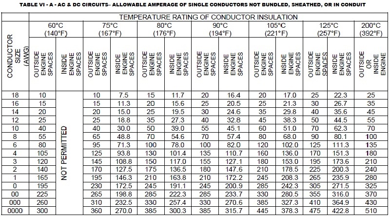
- wire sizing: 2AWG for the busbar<->inverter connections (1500w % 0.85 for derating % 12.8v) -> 137A...
- do the battery<->busbar cables need to also be the same size? They shouldn't, as these will not carry more than X/N worth of current, where X is the total current across the busbar and N is the number of batteries, right? Would I need to assume that at some point things fail to where there's a single battery powering the whole thing? Or do I just find whatever current value the BMS will cut-out, and size the wires for that?
- wire length: I think that the cable lengths need to be {P1=P2=P3=P4) and (N1=N2=N3=N4). I don't think that P0=N0, right? Isn't the requirement that all of the positive runs need to be the same total resistance, and all the negative runs need to be the same length? Or did I miss something here as well?
")
- separate BMS: the individual batteries all have their own internal BMS, but does it make sense for me to add some kind of external one to try and keep the 12v batteries balanced? and if so, what sorts of ratings do I need for the BMS?
Thanks again for all the super useful info so far...
Last edited: