diy solar

diy solar

120V on the PV line?? Discussion of Will's video

FilterGuy

Solar Engineering Consultant - EG4 and Consumers
Joined
Nov 26, 2019
Messages
7,939
Location
Los Gatos CA
@Will Prowse just did a video warning folks about 120V showing up on the PV lines.


There have been several threads where people reported seeing voltage on the PV out. I always thought it was failed units, but Will reports it is normal on a lot of units.

I can kinda understand if the 120V is measured between the PV lines and ground, but I *really* don't understand how it would be OK to have 120V between the two PV lines. Wouldn't that be driving current through the panels?

What are people seeing? If you have seen this, please report what you have seen: Make, Model and what you are seeing? (Do you see 120 between the two PV lines or just 120 between one or both of the PV lines and ground?).


By the way: Will states that you should not ground your panels... I am pretty sure he means you should not ground one of the power lines from the panels. The panel frames are required to be grounded in the NEC.
 
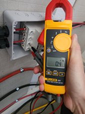
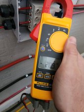
First version eg4 6500ex has 20VDC and nearly 0VAC on input when inverter is on. I did not test with AC input connected to grid.
20230216_104310.jpg20230216_104336.jpg

The eg4 6K has 60V .16A on PV input when shorted to ground with 10K resistor. Also makes a buzzing noise when you short the terminals to ground. And arcing.

Original MPP lv6548 has varying voltage but it gets pretty high when it does.

I tested another model which is a prototype that has solid 120VAC at PV terminals. This one was dangerous and blew my meter.

Growatts seem to have same issue and multiple people in my videos comment section reported getting shocked by those units.
 
EG4 6500
When I was rewiring my PV disconnects, I saw 35v on my connections.
 
@Will Prowse just did a video warning folks about 120V showing up on the PV lines.


There have been several threads where people reported seeing voltage on the PV out. I always thought it was failed units, but Will reports it is normal on a lot of units.

I can kinda understand if the 120V is measured between the PV lines and ground, but I *really* don't understand how it would be OK to have 120V between the two PV lines. Wouldn't that be driving current through the panels?

What are people seeing? If you have seen this, please report what you have seen: Make, Model and what you are seeing? (Do you see 120 between the two PV lines or just 120 between one or both of the PV lines and ground?).


By the way: Will states that you should not ground your panels... I am pretty sure he means you should not ground one of the power lines from the panels. The panel frames are required to be grounded in the NEC.
I'm going to be taking mine offline to rework some cabling in the next day or two and I'll check it and post what I find. On grounding the panels, I believe Will mentioned it in the video or the comment section and did state that he was referring to the negative PV cable, and that the frames should definitely be grounded. I'm just trying to figure out why anyone would connect the negative cable on the panels to ground. I suppose it's one of those terminology things that can bite you in the ass.
 
I'm going to be taking mine offline to rework some cabling in the next day or two and I'll check it and post what I find. On grounding the panels, I believe Will mentioned it in the video or the comment section and did state that he was referring to the negative PV cable, and that the frames should definitely be grounded. I'm just trying to figure out why anyone would connect the negative cable on the panels to ground. I suppose it's one of those terminology things that can bite you in the ass.
Grounding DC circuits is common. In fact, one of the ways the PV Ground Fault Protectors works grounds the PV negative through a 1/2A breaker. If the current between the PV line and ground goes above 1/2 amp, the breaker pops, and a larger breaker ganged to the first opens the Positiv line. This type of PV Ground Fault protection obviously can not be used on these inverters. Instead, the GFPD must use a Hall Effect sensor around the two lines to detect a differential current and open the PV if the differential current gets above a certain threshold. This is one of the reasons it is so difficult to set these inverters up in an NEC-compliant way.
 
First version eg4 6500ex has 20VDC and nearly 0VAC on input when inverter is on. I did not test with AC input connected to grid.
View attachment 135555View attachment 135556

The eg4 6K has 60V .16A on PV input when shorted to ground with 10K resistor. Also makes a buzzing noise when you short the terminals to ground. And arcing.

Original MPP lv6548 has varying voltage but it gets pretty high when it does.

I tested another model which is a prototype that has solid 120VAC at PV terminals. This one was dangerous and blew my meter.

Growatts seem to have same issue and multiple people in my videos comment section reported getting shocked by those units.
Thanks Will! I am curious how when in bypass, 65W is measured draw from the batteries and when in battery mode, there is AC draw around 65 watts. The logic doesn’t make sense to me or others. There is no immediate relational reason why idle should be divided between inputs. This is what came to my mind when I read your findings of unexpected voltage types in the wrong input/outputs. Thoughts?
 
I measured DC and AC between PV+ and PV-, 398 VDC from PV, 3.35 Vrms ripple for a transformer isolated GT PV inverter:


This was a negative-grounded PV string (inside the inverter) so no other ripple would be present common-mode.
Smaller capacitors would have meant larger differential-mode ripple.

I could imagine a transformerless inverter having common mode, if it was a Buck converter with PV- riding the negative half of AC and PV+ being stepped down to the positive half.

SMA's transformerless GT PV inverters have a spec for maximum PV panel capacitance to ground, which results in leakage current due to superimposed AC. I think I did not see that superimposed AC when used on split-phase (although it will bounce during power-up test for shorts to ground). When used on two legs of 3-phase 120/208Y, it is going to orbit at 60 Vrms.
 
Grounding DC circuits is common. In fact, one of the ways the PV Ground Fault Protectors works grounds the PV negative through a 1/2A breaker. If the current between the PV line and ground goes above 1/2 amp, the breaker pops, and a larger breaker ganged to the first opens the Positiv line. This type of PV Ground Fault protection obviously can not be used on these inverters. Instead, the GFPD must use a Hall Effect sensor around the two lines to detect a differential current and open the PV if the differential current gets above a certain threshold. This is one of the reasons it is so difficult to set these inverters up in an NEC-compliant way.
This is why I hang out here. I'm getting a lot of education and not made to feel like an idiot in the process. Okay, sometimes I make myself feel like an idiot, but y'all never point it out. :)
 
iu
 
@Will Prowse just did a video warning folks about 120V showing up on the PV lines.


"Never heard anyone mention this issue" - forum members have described getting a shock from unconnected PV input.

@Will Prowse Disconnecting battery and grid inputs alone isn't enough. Need to also wait a while for charge on PV input capacitors to drain away. So check voltage of those too before starting work. Most of my SMA inverters, it says wait 15 minutes or so. I'm impatient, of course. When I see the LCD display go blank it is ready. At that point, the 400V has drained to about 30V.

The Sunny Boy 5000US I'm presently using says,

"1. Switch off all AC and DC breakers or switch-disconnectors. Ensure they cannot reconnect
accidentally.
2. Wait at least 5 minutes until the residual voltage has been drained."

MC connectors on inverter makes it easy to just connect PV+ and PV-, not think about ground. Need a separate ground wire from PV frames back to inverter. That will protect against shock from damaged or leaky module (some old Trina modules developed leakage), also protects against AC leakage current through PV panel capacitance.

When conduit is used for PV runs it is easier to include ground, and terminals may remind you.

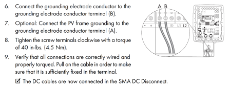
I find mention of grounding PV panel frames in Sunny Boy 10000TL-US-12:

1676777806768.png

And the current SB5.0-1SP-US-41: "• Only ground the mounting frames of the PV modules."
And the earlier 5000US:

"PV Grounding
The grounding conductor in the framework of the PV array must be connected to the PV grounding
conductor and the DC grounding conductor (see section 4.2 ”Locating Internal Component Parts”
(page 20)). The cross-section of the grounding conductor corresponds to the cross-section of the
largest conductor in the DC system."
 
"Never heard anyone mention this issue" - forum members have described getting a shock from unconnected PV input.

@Will Prowse Disconnecting battery and grid inputs alone isn't enough. Need to also wait a while for charge on PV input capacitors to drain away. So check voltage of those too before starting work. Most of my SMA inverters, it says wait 15 minutes or so. I'm impatient, of course. When I see the LCD display go blank it is ready. At that point, the 400V has drained to about 30V.

The Sunny Boy 5000US I'm presently using says,

"1. Switch off all AC and DC breakers or switch-disconnectors. Ensure they cannot reconnect
accidentally.
2. Wait at least 5 minutes until the residual voltage has been drained."

MC connectors on inverter makes it easy to just connect PV+ and PV-, not think about ground. Need a separate ground wire from PV frames back to inverter. That will protect against shock from damaged or leaky module (some old Trina modules developed leakage), also protects against AC leakage current through PV panel capacitance.

When conduit is used for PV runs it is easier to include ground, and terminals may remind you.

I find mention of grounding PV panel frames in Sunny Boy 10000TL-US-12:

View attachment 135565

And the current SB5.0-1SP-US-41: "• Only ground the mounting frames of the PV modules."
And the earlier 5000US:

"PV Grounding
The grounding conductor in the framework of the PV array must be connected to the PV grounding
conductor and the DC grounding conductor (see section 4.2 ”Locating Internal Component Parts”
(page 20)). The cross-section of the grounding conductor corresponds to the cross-section of the
largest conductor in the DC system."
Would grounding the panel frames to your earth ground (only one earth ground and only bonded to N in the main panel) not accomplish the same thing? Asking for a friend ...
 
Asking for a friend ...

⚡?⚡ 1676779788646.png ?

Nope. Residential ground rods in California might be 25 ohms to earth.

Without current flowing through earth, that is good enough to pull an otherwise floating system to same potential as dirt, so if you're standing on the ground touching metal objects, no potential across you and no current through you.

My PV array is about 380Vmp, 480Voc, and some PV strings are negative grounded at the inverter.
If PV+ shorted to frame, that 25 ohms at the frame ground rod, and 25 ohms at house ground rod (or maybe lower if tied in to foundation steel) would set up a voltage gradient across the earth. "Step potential", so if you walked on the ground with bare feet you might get a shock. (Situations of downed power line, instructions are to not take big steps, rather keep your feet together and shuffle away.)

A copper wire, sized to carry PV current continuously (Isc x 1.56) keeps frame at same voltage, so no current flow.

Your PV string might be good for driving nightcrawlers to the surface, if you want to go fishing.


You can do that with a hand crank generator (from an antique telephone), and then you'll be sure to stop cranking before walking across the lawn.
If you do that with a PV panel, don't forget to open the circuit first.

iu
 
⚡?⚡ View attachment 135568 ?

Nope. Residential ground rods in California might be 25 ohms to earth.

Without current flowing through earth, that is good enough to pull an otherwise floating system to same potential as dirt, so if you're standing on the ground touching metal objects, no potential across you and no current through you.

My PV array is about 380Vmp, 480Voc, and some PV strings are negative grounded at the inverter.
If PV+ shorted to frame, that 25 ohms at the frame ground rod, and 25 ohms at house ground rod (or maybe lower if tied in to foundation steel) would set up a voltage gradient across the earth. "Step potential", so if you walked on the ground with bare feet you might get a shock. (Situations of downed power line, instructions are to not take big steps, rather keep your feet together and shuffle away.)

A copper wire, sized to carry PV current continuously (Isc x 1.56) keeps frame at same voltage, so no current flow.

Your PV string might be good for driving nightcrawlers to the surface, if you want to go fishing.


You can do that with a hand crank generator (from an antique telephone), and then you'll be sure to stop cranking before walking across the lawn.
If you do that with a PV panel, don't forget to open the circuit first.

iu
I wasn't clear on that, I suppose. My panel frames are not grounded to a separate earth ground. They are ground back to the earth ground for my system. The entire system has one earth ground.
 
Yes, that is good. A wire back to the rest of the system, which is grounded to earth.

Code may require additional rods elsewhere. I have two buildings, one with a main breaker panel and one with a sub panel. Each has a ground rod (required, as I understand) and they have ground wire between them, also to their pipes.

I'm not sure if/when a PV rack is supposed to have its own ground rod. Given ground wire back to system, I don't think even carrying Isc the frame would be elevated much above earth. But it could be if there is a fault in some other high voltage power system, there is a voltage gradient across the earth. Imagine if that was 1V/meter. You wouldn't notice it walking, but if you touched a frame that wasn't grounded locally, but rather had a wire running 100 meters away and grounded there (at your system), the frame could be 100V above ground. The code may seek to address that.
 
I finally got around to testing mine this afternoon after I did some re-cabling and cleanup. I have zero voltage on the PV connections on either inverter. Here's the scenario of my test -

Battery and battery breaker turned off
Solar input turned off at disconnect
No load
AC input turned on - 120v on AC input on both inverters

Testing all the PV input I had zero voltage on any of them. I tested both AC and DC voltage, although the situation in question was only AC.

These are two MPP LV6548 configured for split phase 240.

I do have the grounding screw removed on the primary inverter but I can't see where that would matter, and I do have everything grounded back to the earth ground on the main panel only.

I'm not complaining, but it's a little strange that everyone else is getting a range of AC voltage on the PV inputs and I'm not. Maybe y'all can figure it out. I'm thinking it's time for a Shiner Bock myself.
 
Back
Top