Small bridge is not same as tall bridgeHi, Im not sure about your background but I am a mechanical engineer and have constructed all kind random products for a profession. I'm sorry to say but a HEB600 by itself would never ever be used for a tall bridgeYou usually have either massive towers with wires helping with the support between towers or you use a structure below road surface so the total thickness of the surface below the car is way more than 600mm. I dont have Inventor on this Computer so I didnt do a FEM analysis myself, Ijust calculated with E module as 2.1x10^5 which is common for normal steel and used Eulers case with 1 fixed point and the second free hanging. If you show me your calculation I guess we can see where it has been wrong. But the whole area of the thing blowing with a pressure of +110kg/sqm will be 2.4x2x6x110 = 3200kg and to simplify you can put that as one force on middle of beam = 3m up on the beam. And you can load it some more before plastic deformation occur but not much and the HEB 500 will not handle the +3000kg load. Can you show your calculation and we can compare?
Different sort of engineer (EE-ish) here but can calculate enough to tell that HEB600 is not going to bend by couple solar panels.
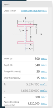
I did my crude calculation from HEB600 flange dimensions, flange distance and calculated tensile stress in the beam flange.
30x300mm flange, S355 steel gives us 3195 kN tensile yield strength for the flange. Distance from flange to flange is abouts 600mm and assuming that the flange handles 100% of the load and web is just dead weight.
600mm distance from flange to flange and 6000 mm beam length gives nice round 1:10 ratio on lever arms and torque.
320kN at 6m is 1920 kNm, with 0.6m meters between the flanges it translates to 1920 kNm/0.6m=3200 kN tensile stress on beam flange.
Just to make sure that we are talking about same HEB600 here:
If you mixed up HEB600 and HEB60 I'd buy it but then on the other hand I hope I don't cross too many bridges that are your design.