Ok I do not have a victron protect or any victron products. But this whole thread makes me a scratch my head. If it can't be used for what it has been used for by will and many others. What is it's purpose. Why does it have different amp ratings if it can't handle large loads. The data sheet says a 220 amp BP can handle up to 600 amps peak current. So what's it for?


You are using an out of date browser. It may not display this or other websites correctly.
You should upgrade or use an alternative browser.
You should upgrade or use an alternative browser.
3000W Inverter/charger connection to BMS/Battery question
- Thread starter Starry-Nights
- Start date
gnubie
Solar Wizard
- Joined
- Sep 20, 2019
- Messages
- 3,847
The problem from my understanding is that the inverters people are hooking onto them have quite large input capacitance and the resulting extremely high currents and the very quick rise time of that current pops the device. If the inverter's capacitors are precharged, as they really should be, all will be good. If an inverter that doesn't have great gobs of capacitance across its DC input is used, all will be good.
Suppose you have a BP and it does it's job and shuts the inverter off. When the BP turns inverter back on won't the Caps suck up a large load. Especially if inverter is powering something when power is shut offThe problem from my understanding is that the inverters people are hooking onto them have quite large input capacitance and the resulting extremely high currents and the very quick rise time of that current pops the device. If the inverter's capacitors are precharged, as they really should be, all will be good. If an inverter that doesn't have great gobs of capacitance across its DC input is used, all will be good.
SilverLiningSolar
New Member
I was looking at that relay - it shows 24 Volts in spec, but 12 volts on the image. Would that be rated for 24v max and activated by 12v?
Bluemalibu
New Member
Holy Moly !!!
I am SO GLAD that this has come to light now! I just spent $3200 on a LifePO4 battery bank that I intend to outlive me, and am using the 24v Blueprint as a guide for assembly. As a military retiree, I can assure you that I certainly don't have the loose change lying around with which to replace these batteries.
And I must be living right, as I am even still within the window to be able to return the Victron BP to Amazon, and was able to grab the very last 500a relay suggested above, from the website. ;-)
Bluemalibu
New Member
So, a couple of questions....
If one is using batteries with built-in sealed BMS, how might an external BMS be wired to trip the relay? Perhaps simply connect the cell leads of the BMS to the battery + post, in order to gauge the voltage of the battery? Or might an alternate triggering mechanism be better in this situation @Will Prowse ?
And secondly, doesn't a latching relay, such as is linkeded above, close upon receiving a pulse of energy to terminal 86 (accomplished by the negative terminal 85 closing the circuit via the BMS) and then require a second impulse across these terminals in order to trigger the release the magnet that accomplishes the circuit closure across terminals 87 / 30?
This was my understanding, as how it differs from a non-latching relay, which only requires the opening of the 86 / 85 circuit in order to open the 87 / 30 circuit.
Last edited:
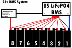
ok. I don't consider myself dumb, but it has been a long day....and Im not very experienced with relays. I have (6) 8s lifepo4's (24v). Each with a Daly 8s bms. All the negs from the bms' going to a neg bus bar (paralleled at that point). Do I need 8 of the relays then?
One of the great benefits of the Victron BatteryProtect units is their tiny current draw while "on". Now with these updated suggestions to use a mechanical relay, the relay coil will be drawing a certain amount of power 24/7 to keep the relay turned on.
While I realise that the relay coil current draw is probably less than the inverter's no-load current draw, I have a small system tend only to switch on my inverter when needed. Now I will also have to put a switch inline with the relay coil and remember to switch that off too.
Do less expensive equivalents of the mentioned Sterling ProLatch-R exist? Or a less expensive bistable relay that can be driven by a low-voltage-detect unit that supports bistable relays? The 240A version is over double the price of the 220A victron batteryprotect.
From a "modern electronics" perspective - surely there is must be a better way. It seems like a retrograde step to go from silent, low-power, solid-state mosfets, controlled by bluetooth, with multiple modes and voltage thresholds, to mechanical coils and contacts, especially with the potential for arcing with RFI and contact erosion when they disconnect.
ScoTTyBEEE
New Member
- Joined
- Sep 23, 2019
- Messages
- 112
If your inverter has a remote relay just use the small cheap battery protect for your 12v side and get it to trip the inverter remote and turn that off.
a 200A relay will draw around 0.5A continuous, 12A a day, which is a bit crappy, but manageable.
a 200A relay will draw around 0.5A continuous, 12A a day, which is a bit crappy, but manageable.
If your inverter has a remote relay just use the small cheap battery protect for your 12v side and get it to trip the inverter remote and turn that off.
Sure, I could do that, but some things bother me about it:
- I'm reliant on the inverter not to misbehave. The BatteryProtect was completely independent of the inverter. (I have a cheap inverter. I don't trust it to turn off).
- If I don't have 12V loads, I've just bought a 65A switch to switch a logic input to the inverter.
- While my inverter does have a remote switch socket, the vendor is being reluctant to give me the pinout. Some inverters don't have a remote at all.
It all seems like a boatload of compromises.
Bluemalibu
New Member
One of the great benefits of the Victron BatteryProtect units is their tiny current draw while "on". Now with these updated suggestions to use a mechanical relay, the relay coil will be drawing a certain amount of power 24/7 to keep the relay turned on.
Do less expensive equivalents of the mentioned Sterling ProLatch-R exist? The 240A version is over double the price of the 220A victron batteryprotect.
I went ahead and sprung for the ProLatch-R. It only draws 0.5mA, vs. the .45A parasitic draw from a non-latching relay. So, it really is false economy to purchase the cheap relay when you factor in the power loss over the long run. And Amazon is offering the 240A unit for $159... so, just $43 more than the 220A smart BP from Victron.
$159 is awfully cheap insurance to safeguard a $3200 battery bank.
Starry-Nights
New Member
- Joined
- Nov 4, 2019
- Messages
- 23
Inverters have an even larger draw when not in use! In my van I have tried to make everything possible run on DC. I have a remote on/off switch for the inverter and only turn it on when I need to run something like the induction cooktop. How about adding a switch that when the inverter is off, it would bypass the relay (terminals 85 and 86)?
Steve_S
Offgrid Cabineer, N.E. Ontario, Canada
Good Question, there are a lot of people using batteries with built in BMS and various types and this is a good question which should be answered, in doc's tut's & vid's.If one is using batteries with built-in sealed BMS, how might an external BMS be wired to trip the relay? Perhaps simply connect the cell leads of the BMS to the battery + post, in order to gauge the voltage of the battery? Or might an alternate triggering mechanism be better in this situation @Will Prowse ?
Bluemalibu
New Member
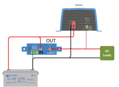
Victron's solution to allow the continued use of their BP with inverters was dead-simple. We simply do not route the B+ through the Battery Protect, to the DC 'IN', on the inverter. In this way, the heavy current surge to initially charge the capacitors does not flow through the BP, while still allowing it to monitor the SoC and take the inverter out of the circuit at the voltage that we specify.
And this also side-steps the expenditure of .45 amps of parasitic draw required by the use of a 200 amp non-latching relay.
And this also side-steps the expenditure of .45 amps of parasitic draw required by the use of a 200 amp non-latching relay.
Greenan_Energy
New Member
- Joined
- Dec 2, 2019
- Messages
- 67
Bluemalibu I understand that the BP can monitor the the voltages. But if its not going through the BP, how can it cut it off. Thanks
Bluemalibu
New Member
The power 'out' from the BP is energizing the remote power switch on the inverter.
Greenan_Energy
New Member
- Joined
- Dec 2, 2019
- Messages
- 67
Thanks man
Hi - I presume I'm missing something here, but in Will's schematic the negative line from the SCC (charging load) is connected directly to the battery negative. I though that this was supposed to be connected to the P- side of the BMS, so that the BMS can manage the charging of the battery. Doesn't the wiring shown bypass the BMS for the charging? So you wouldn't get the low temp cut-off from the BMS for charging?
The issue I'm having is that I'm designing a system with a relay on the inverter as discussed, but have my SCC negative line connected to the P- side of the BMS, which is what is suggested by the instructions on Overkill Solar and makes sense to me. However, if I do this, then the positive and negative trigger loads for the relay will be connected to the SCC, and therefore if the SCC is providing a charging load, the relay will be activated. Therefore, even if the BMS cuts out from low voltage, the relay would still potentially get load from the solar charger and not cut the inverter. In the case that the amperage coming from the SCC is less than what is being drawn by the inverter (most of the time) then the battery would continue to be drawn down.
See attached for a schematic of what I'm talking about.
Would appreciate if someone can point out where I'm going wrong with this - thanks!
Note: Yes I know the panels are very small for the size of the battery bank - panels will be upgraded in the future.
Attachments
Hey! If I want to use an inverter with bms can I connect as shown?I have a eight 100 amp 3.2V LiFeP04 cells connected as a 100 amp 24V battery with a Daly 8S 24V 200amp BMS. I also have a 3000W / 9000W surge Inverter Charger. The BMS has 6 AWG cables which seem nowhere near the required 1/0 AWG minimum for the inverter. I at first thought of connecting the inverter directly to the battery, and not through the BMS first, but that would seem it could make the BMS completely bypassed. I have looked at some other BMS's but the cables on them seem pretty wimpy too. Suggestions, simple wiring diagram greatly appreciated!
One additional related question: I am using a Epever 30Amp MPPT and live in NH where the temps have starting dropping into the 20's at night. The controller has a Temp sensor, but I can find no setting to stop charging when temp goes below freezing. The Daly BMS does not seem to have this capability either. To handle, I have installed a simple thermostat the cuts the solar array off at 34 degrees and resumes and 37. It has a 20 amp relay and it works great for the solar (four 100W panels, configured as 24V), but would not work for the higher amps of the inverter/charger. Additionally, I have a 12V to 24V Sterling Battery to Battery unit I have yet to install that can supply up to 70 amps.
Attachments
Similar threads
- Replies
- 2
- Views
- 121