diy solar

diy solar

6000XP’s/Ruixu Batteries in Production for Home UPS System

BrianVeg

New Member
Joined
Sep 19, 2023
Messages
77
Location
Michigan
Well I’m finally done and my system is in production.

My goal when I started this phase (Phase 1) of the project was to create an expandable system that would act as a backup for my critical circuits for 24 hours during a power outage. While I have not quite hit that goal, I’m at 15:45 with the current batteries. My calculations of energy used were off. Oh well - still happy!

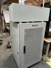
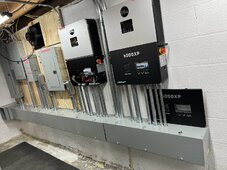
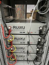
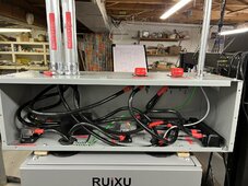
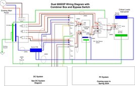
My system consists of 2 X 6000XP’s with 4 x Ruixu batteries. I also have AC connected to provide the primary source of energy for my UPS until I get solar.

I set the 6000XP’s with AC Grid first with a time slot of 00:00 to 23:59

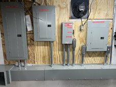
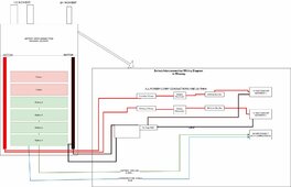
I posted some pictures here to show my system and the wiring diagrams I used.

This forum has been a great resource for putting this together specifically @FilterGuy and @AZ Solar Junkie for their help.

Current Connected @HighTechLab was also very helpful in selling and supporting my installation.

Time for inspection and on to planning for my panels!
 

Attachments

  • IMG_0657.jpeg
    IMG_0657.jpeg
    219.2 KB · Views: 104
  • IMG_0656.jpeg
    IMG_0656.jpeg
    248.3 KB · Views: 93
  • IMG_0655.jpeg
    IMG_0655.jpeg
    311.1 KB · Views: 99
  • IMG_0652.jpeg
    IMG_0652.jpeg
    232.5 KB · Views: 96
  • IMG_0647.jpeg
    IMG_0647.jpeg
    283.3 KB · Views: 101
  • Solar Project-DC System.jpeg
    Solar Project-DC System.jpeg
    104.6 KB · Views: 98
  • Solar Project-Copy of 6000XP Wiring Diagram.jpeg
    Solar Project-Copy of 6000XP Wiring Diagram.jpeg
    182.5 KB · Views: 89
Looks awesome, man. Very clean and nice. I have just 2 concerns:
  1. Lack of an earth ground connection to your second inverter. All equipment needs one for safety.

  2. I'm not a code guy, but I'm a little concerned from a code perspective about the unprotected wires I see - like the romex coming out of your combiner panel and other wires going to your critical loads panel. It might be totally fine, but might want to double-check on code requirements there. @FilterGuy @timselectric - would that pass inspection?
In a mechanical room, I think he is just fine. Might be missing a staple but we are really nitpicking now.
 
Lack of an earth ground connection to your second inverter. All equipment needs one for safety.
That somehow got deleted from the diagram. It’s there.

Just updated the diagram

I'm a little concerned from a code perspective about the unprotected wires I see - like the romex coming out of your combiner panel and other wires going to your critical loads panel
That’s the way my main panel is setup, so it should be okay.
 
Last edited:
That diagram looks familiar :ROFLMAO:.


Did I steal the design from you, or did we both steal it from someone else? ;) Congrats on getting to this point!
 
Thanx!

Yeh it does. @FilterGuy had an image in that thread that I started from, I needed it to be in draw.io to make the mods I wanted. So I forked it! (I live in an open source software world) 😂

He helped me tremendously with his comments.

In the big picture I’m not sure it matters, that’s what this community is all about!
 
I'm a little concerned with my settings. Running in AC Grid First mode draws quite a bit more power (~15%) than just the loads as it is trying to keep the battery charged.

What I want to do is to charge the batteries to 100% and then put the inverters in Bypass Mode and wait for a power failure.

@AZ Solar Junkie has a nice explanation on increasing efficiency by using the ECO Mode and On Grid EOD SOC % to get the inverters in bypass mode until the batteries are 10% above the On Grid EOD SOC %.


I have implemented his suggestion slightly differently given my use case.
  • ECO Mode - On
  • On Grid EOD SOC % = 90% (max)
I was able to discharge my batteries to 90% and the inverters switched to Bypass mode - Works Great!

However, given that I would want to maximize the time my batteries will run without grid I'm not sure I like that option either.

Right now I see two options:
  • Option 1 - Lower Efficiency with longer runway until batteries discharge (AC Grid First - 24 hours/ day - batteries always at 100% - grid power runs ~15% higher than load power)
  • Option 2 - Higher Efficiency with shorter runway until batteries discharge (On Grid EOD SOC % = 90% with virtually identical load and grid power)
Am I missing an option?
I don't think you're missing an option. I do think the firmware is missing some options to make it work the way you would like. Some setting thresholds that explicitly control when the inverter is in bypass would be nice...

What happens when the batteries get down to the On Grid EOD SOC % if you have no grid? I haven't actually tested that.
 
@AZ Solar Junkie - I did part of the test today. With grid on and the On Grid EOD SOC % set to 90%, I discharged the batteries with the system in UPS Mode. Once the batteries got down to 89% the system as expected went into bypass mode and operated fine.

After an hour of so I then killed power and the system switched back to UPS mode and continued to discharge the batteries. So that worked.

I do not have time today to discharge the batteries all the way to Discharge Cut-off SOC %. I'll leave that for another day next week when I can be here as the batteries get down to Discharge Cut-off SOC %.

I do agree that something that allows us to explicitly put the system in Bypass Mode is needed.
 
However, given that I would want to maximize the time my batteries will run without grid I'm not sure I like that option either.
I'm not usually on the side of babying batteries, but for a standby application, I'd be uncomfortable holding over 90% all the time.
 
@hwy17 Right now they are sitting at 89%. But I am curious as to why your uncomfortable with holding over 90%.
I believe higher states of charge accelerate degradation and the difference between 100 and 90% is bigger than 90 and 80%. I.e. giving up that first 10% gives the most benefit.
 
Back
Top