chilly2
New Member
- Joined
- Sep 14, 2021
- Messages
- 156
Hello!
As I write another blissfully sunny day has both covered the house load and filled my 5kWh of storage before 2pm. I'm fairly certain a second 5kWh, or a good percentage of it at least, could be filled before the end of the day, so I'm thinking about adding a server rack 5kWh battery.
Current configuration...
48v system.
5kWh battery (4S 12.8v LiFePO4s, AWG 2/0 connections), with active balancer. Referring to as 4S from here on in.
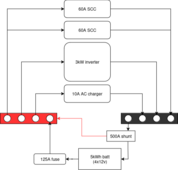
The charge controllers (2x), 4S and inverters share a single set of 4 bolt bus bars.
There's a 125A ANL fuse on the +ve and a Victron smart shunt on the -ve from the 4S.
The plan...
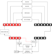
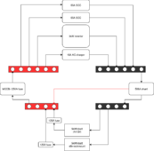
- Move the charge controllers and inverters to a second set of bus bars.
- Join the two sets of bus bars with 2/0.
- Connect a new server rack 5kWh battery to the free spaces on the original bus bars.
The questions...
- Compatibility - The 4S are about 8 months old now. Would there be any problem having them in parallel with a rackmount battery?
- Safety - as above there's a fuse on the +ve but no switch or anything to cut off the 4S. What sort of fuse / switch should I put in between the two sets of bus bars to protect the CCs & inverters?
- Monitoring / SOC across multiple batteries - The smart shunt shows the SOC on the 4S. What would be the best way to keep an eye on the 4S and the new battery, preferably in one place? Another smart shunt seems expensive. Can I put the existing shunt on the -ve between the sets of bus bars and see the SOC across the batteries as a whole (up to 10kWh)? I realise I lose visibility on the 4S if I do that. Of the new batteries I've looked at, one has RS485, and one has a screen and bluetooth app so I could get by that way.
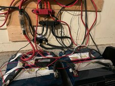
As a picture tells a thousand words, here's the current rats nest. It looks worse than it is but it's working fine, nothing overheating, etc. The bus bars are full, so the new battery is the impetus to reorganize the setup.
Critique of the plan / suggesions of other schematics welcome!
As I write another blissfully sunny day has both covered the house load and filled my 5kWh of storage before 2pm. I'm fairly certain a second 5kWh, or a good percentage of it at least, could be filled before the end of the day, so I'm thinking about adding a server rack 5kWh battery.
Current configuration...
48v system.
5kWh battery (4S 12.8v LiFePO4s, AWG 2/0 connections), with active balancer. Referring to as 4S from here on in.
The charge controllers (2x), 4S and inverters share a single set of 4 bolt bus bars.
There's a 125A ANL fuse on the +ve and a Victron smart shunt on the -ve from the 4S.
The plan...
- Move the charge controllers and inverters to a second set of bus bars.
- Join the two sets of bus bars with 2/0.
- Connect a new server rack 5kWh battery to the free spaces on the original bus bars.
The questions...
- Compatibility - The 4S are about 8 months old now. Would there be any problem having them in parallel with a rackmount battery?
- Safety - as above there's a fuse on the +ve but no switch or anything to cut off the 4S. What sort of fuse / switch should I put in between the two sets of bus bars to protect the CCs & inverters?
- Monitoring / SOC across multiple batteries - The smart shunt shows the SOC on the 4S. What would be the best way to keep an eye on the 4S and the new battery, preferably in one place? Another smart shunt seems expensive. Can I put the existing shunt on the -ve between the sets of bus bars and see the SOC across the batteries as a whole (up to 10kWh)? I realise I lose visibility on the 4S if I do that. Of the new batteries I've looked at, one has RS485, and one has a screen and bluetooth app so I could get by that way.
As a picture tells a thousand words, here's the current rats nest. It looks worse than it is but it's working fine, nothing overheating, etc. The bus bars are full, so the new battery is the impetus to reorganize the setup.
Critique of the plan / suggesions of other schematics welcome!
")