You are using an out of date browser. It may not display this or other websites correctly.
You should upgrade or use an alternative browser.
You should upgrade or use an alternative browser.
CAN and RS485 BMS Interface with multiple emulated Inverter protocols for JkBms Jbd BMS Daly 123Smart
- Thread starter mrconstantin
- Start date
mrconstantin
New Member
yes,ok, but then i need 3rd jkbms, it has max 24s. is possible to test set 3,75V and load it to let say 4V? of course capacity will be small, but to test funcionality will be enough?
but u have some problems
u want an hv setup, the GND of jkbms 1 can not be same with jkbms 2 that why u need to take data thrue rs485 or can, usuly for hv setup use jk balancer with can port and u can cascade them , jk bms can not be cascade.
so, better use one jkbms + 2 jk balancer? As I understand, only 24s will be under switch control of jkbms, rest i need have external switch - maybe related to jkbms. jk balancers will be connected to jkbms by cam, and all information about whole set will be from jkbms.
mrconstantin
New Member
to cut the pack from the invertor u have external switch.so, better use one jkbms + 2 jk balancer? As I understand, only 24s will be under switch control of jkbms, rest i need have external switch - maybe related to jkbms. jk balancers will be connected to jkbms by cam, and all information about whole set will be from jkbms.
some invertor dont need to send amp readings from bms and u can use only jk balancers for ur pack, some need amp reading from bms and in this case u need a curent sensor. I use an JKbms only for the current sensor , but in the end i will find a better option for that sensor because i am not 100% satisfy.
mrconstantin
New Member
MarcelVo
New Member
Hi,
I will present my DIY CAN BMS emulator project , I work from some time to make this interface for integration of DIY battery with different brands of invertors with supported CAN or RS485 communication.
Interface use an esp32 with one or tow CAN ports and RS485 support, can handle multiple JK as inputs for data, and also cand handle LV or HV.
I use in this project all the data i can find online, i know am not the first on this road if u have documents of other BMS protocols u can share it with me.
If u want u can support my work to add more protocols to this project and buy the hardware components kit from my ebay or fallow on Patreon!
Hardware:
Esp32 DevKit 1
CAN : SN65HVD230
RS485: Max485
DC-DC: XL7015
RJ45 Breakout
Optional: Indicator LEDs
View attachment 156678
View attachment 156679
Connectivity:
WIFI Web Portal with Cell Info Data on local IP
View attachment 156673
View attachment 156676
Input BMS supported:
View attachment 156674
JK BMS - TTL, BT , CAN
JBD BMS - BT connection
Daly - work in progress
Protocol Emulated:
View attachment 156675
General BMS LV
Document V1.4 - 07.09.2020
CAN: 500Kbps
Transmission Cycle: 1s
Data Mode: Little Endian
Pylonthech LV
Document V1.2 - 08.04.2018
CAN: 500Kbps
Transmission Cycle: 1s
Data Mode: Little Endian
Seplos LV
Document V1.0 - 08.04.2018
CAN: 500Kbps
Transmission Cycle: 1s
Data Mode: Little Endian
LG Resu LV
Document
CAN: 500Kbps
Transmission Cycle: 1s
Data Mode: Little Endian
Growatt LV
Document V1.04 22,02,2019
CAN: 500Kbps
Transmission Cycle: 1s
Data Mode: Big Endian
SMA LV
Document V1.0 - 07.09.2020
CAN: 500Kbps
Transmission Cycle: 1s
Data Mode: Little Endian
Li LV
Document V1.0 06.01.2020
CAN: 500Kbps
Transmission Cycle: 1s
Data Mode: Little Endian
Victron Nemea200
Document V1.0 06.01.2020
CAN: 250Kbps
Transmission Cycle: 1s
Data Mode: Little Endian
Pylon HV
Document V1.18 30.05.2019
CAN: 500Kbps
Transmission Cycle: 1s
Data Mode: Little Endian
GoodWee HV
Document V1.3 31.03.2021
CAN: 250Kbps
Transmission Cycle: 1s
Data Mode: Little Endian
BYD HV
Document
CAN: 500Kbps
Transmission Cycle: 1s
Data Mode: Little Endian
Pylontec RS485
Document V2.0 15.10.2019
RS485: 9600bps MODUBUS ASCII
Transmission Cycle: 0.5s Timeout
Data Mode: Little Endian
Seplos RS485
Document V3.3 21.08.2018
RS485: 9600bps MODUBUS ASCII
Transmission Cycle: 0.5s Timeout
Inverter Replay:
Data Mode: Little Endian
Growatt RS485
Document V2.02 24.07.2019
RS485: 9600bps MODUBUS ASCII
Transmission Cycle: 0.5s Timeout
Data Mode: Little Endian
BYD RS485
Document
RS485: 9600bps MODUBUS RTU
Transmission Cycle: 1s Timeout
Data Mode: Little Endian
Inverter Tested LV
Victron: Gx Family - General LV have the most information displayed, this is an combination of more registry i find.
Growatt SPF 5000 ES - Pylon LV, Seplos LV, Li LV
Growatt SPH 5000 TL - Pylon Lv, Seplos LV, Li LV, Growatt LV
Solis S5-EH1P6k - Semplos LV, LI LV
Deye SUN12K-SG04 - Pylon LV, LI LV
Inverter Tested HV
Fronius Primo 6.0 Gen24 - BYD HV
SunGrow SH10RT - BYD HV
GoodWE GW10K - GoodWee HV, Pylon HV
ThinkPower S100TL - Pylon HV
MultiPack:
If u have 2 packs with 2 JkBms u can combine data by connected 1 to Serial Port and one on BT Port
If u have more then 2 u need to use more interfaces. The Rs485 will be use to communicate between interfaces and Master CAN port will rapport to bms.
Know Issue:
1 - When u use BT connection u can not connect with the phone app to the JkBMS.
U need to stop the interface power and after connect and make settings with ur phone app.
2 - Pylontech LV - if u use this protocol some inverter limit max charge voltage under 54V for 15S LFP battery.
Use Seplos LV or LI LV protocol is same as pylon with few data changed.
3 - From RS485 Protocols i tested only Fronius Gen24, The Pylon RS485 LV and Semplos RS485 LV are write from documentation for PC App -> Battery communication protocol.
Warranties:
The project is under develop NO WARRANTIES are provided ! USE on ur own RISK!
Software:
In this moment GitHub Repo under construction!
Download & Install:
U can download the bin file from my Google Drive Link and write it on ESP32.
For first install u need to be done with cable an pc, after that u can update the firmware OTA.
i will provide new update as soon i can!
JkBMSCan - Google Drive
drive.google.com
Support my Work:
If u like this project and want to support my work to add more protocols u can invest ur time and also if u can spare some $ will be great too!
Invest Time:
Test the interface on ur inverter and confirm what protocols are compatible to increase invertor compatibility list.
Provide documentation or data communication logs from ur Inverter and OEM battery for reverse engineering new protocols.
Share data if u all ready make some progress on reverse engineering new protocols.
Invest $:
Donate by PayPal and U will receive tech support for ur project!
Fallow on Patreon for last updates.
Buy components kit from my ebay for ur projects.
Documentation:
I share my protocols documentation folder if u want to make ur own software.
if u have any other document of interest share it also with me.
JkBMSCan - Google Drive
drive.google.com
Other Projects :
WifiManager https://github.com/tzapu/WiFiManager
TeslaBMS https://github.com/collin80/TeslaBMS
JKEnuPylon https://github.com/botaneta/JKbms_Emu_Pylon
JKBmsToPylonCAN https://github.com/ArminJo/JK-BMSToPylontechCAN
VictronLibCan https://github.com/jmibk/BMS-LIB-CAN-Victron
Implementation of this interface on battery:
LV 14S 180A Li from Kona with JKBms 150A and Can interface
View attachment 160382
HV 23S / module 60A from Kona with JK Activ Balancer and Can interface
View attachment 160383
JK - Victron
View attachment 160384
JK - Growatt
View attachment 160385
JK - Sungrow
ONLY 10 Pics for post SORRY!
IF U WANT TECH SUPPORT JUST WRITE TO ME, OR WHATUP!
MarcelVo
New Member
Very nice work !!, I am struggeling to get my setup working. I have a DIY 16S 48V Battery with a DALY BMS which does both RS485 & CANBUS; it can emulate different CAN setups. My inverter is a NEDAP / Solar Frontier Power Storage ; which also has a CAN bus (got a few of them, hence my desire to get them to workHi,
I will present my DIY CAN BMS emulator project , I work from some time to make this interface for integration of DIY battery with different brands of invertors with supported CAN or RS485 communication.
Interface use an esp32 with one or tow CAN ports and RS485 support, can handle multiple JK as inputs for data, and also cand handle LV or HV.
I use in this project all the data i can find online, i know am not the first on this road if u have documents of other BMS protocols u can share it with me.
If u want u can support my work to add more protocols to this project and buy the hardware components kit from my ebay or fallow on Patreon!
Hardware:
Esp32 DevKit 1
CAN : SN65HVD230
RS485: Max485
DC-DC: XL7015
RJ45 Breakout
Optional: Indicator LEDs
View attachment 156678
View attachment 156679
Connectivity:
WIFI Web Portal with Cell Info Data on local IP
View attachment 156673
View attachment 156676
Input BMS supported:
View attachment 156674
JK BMS - TTL, BT , CAN
JBD BMS - BT connection
Daly - work in progress
Protocol Emulated:
View attachment 156675
General BMS LV
Document V1.4 - 07.09.2020
CAN: 500Kbps
Transmission Cycle: 1s
Data Mode: Little Endian
Pylonthech LV
Document V1.2 - 08.04.2018
CAN: 500Kbps
Transmission Cycle: 1s
Data Mode: Little Endian
Seplos LV
Document V1.0 - 08.04.2018
CAN: 500Kbps
Transmission Cycle: 1s
Data Mode: Little Endian
LG Resu LV
Document
CAN: 500Kbps
Transmission Cycle: 1s
Data Mode: Little Endian
Growatt LV
Document V1.04 22,02,2019
CAN: 500Kbps
Transmission Cycle: 1s
Data Mode: Big Endian
SMA LV
Document V1.0 - 07.09.2020
CAN: 500Kbps
Transmission Cycle: 1s
Data Mode: Little Endian
Li LV
Document V1.0 06.01.2020
CAN: 500Kbps
Transmission Cycle: 1s
Data Mode: Little Endian
Victron Nemea200
Document V1.0 06.01.2020
CAN: 250Kbps
Transmission Cycle: 1s
Data Mode: Little Endian
Pylon HV
Document V1.18 30.05.2019
CAN: 500Kbps
Transmission Cycle: 1s
Data Mode: Little Endian
GoodWee HV
Document V1.3 31.03.2021
CAN: 250Kbps
Transmission Cycle: 1s
Data Mode: Little Endian
BYD HV
Document
CAN: 500Kbps
Transmission Cycle: 1s
Data Mode: Little Endian
Pylontec RS485
Document V2.0 15.10.2019
RS485: 9600bps MODUBUS ASCII
Transmission Cycle: 0.5s Timeout
Data Mode: Little Endian
Seplos RS485
Document V3.3 21.08.2018
RS485: 9600bps MODUBUS ASCII
Transmission Cycle: 0.5s Timeout
Inverter Replay:
Data Mode: Little Endian
Growatt RS485
Document V2.02 24.07.2019
RS485: 9600bps MODUBUS ASCII
Transmission Cycle: 0.5s Timeout
Data Mode: Little Endian
BYD RS485
Document
RS485: 9600bps MODUBUS RTU
Transmission Cycle: 1s Timeout
Data Mode: Little Endian
Inverter Tested LV
Victron: Gx Family - General LV have the most information displayed, this is an combination of more registry i find.
Growatt SPF 5000 ES - Pylon LV, Seplos LV, Li LV
Growatt SPH 5000 TL - Pylon Lv, Seplos LV, Li LV, Growatt LV
Solis S5-EH1P6k - Semplos LV, LI LV
Deye SUN12K-SG04 - Pylon LV, LI LV
Inverter Tested HV
Fronius Primo 6.0 Gen24 - BYD HV
SunGrow SH10RT - BYD HV
GoodWE GW10K - GoodWee HV, Pylon HV
ThinkPower S100TL - Pylon HV
MultiPack:
If u have 2 packs with 2 JkBms u can combine data by connected 1 to Serial Port and one on BT Port
If u have more then 2 u need to use more interfaces. The Rs485 will be use to communicate between interfaces and Master CAN port will rapport to bms.
Know Issue:
1 - When u use BT connection u can not connect with the phone app to the JkBMS.
U need to stop the interface power and after connect and make settings with ur phone app.
2 - Pylontech LV - if u use this protocol some inverter limit max charge voltage under 54V for 15S LFP battery.
Use Seplos LV or LI LV protocol is same as pylon with few data changed.
3 - From RS485 Protocols i tested only Fronius Gen24, The Pylon RS485 LV and Semplos RS485 LV are write from documentation for PC App -> Battery communication protocol.
Warranties:
The project is under develop NO WARRANTIES are provided ! USE on ur own RISK!
Software:
In this moment GitHub Repo under construction!
Download & Install:
U can download the bin file from my Google Drive Link and write it on ESP32.
For first install u need to be done with cable an pc, after that u can update the firmware OTA.
i will provide new update as soon i can!
JkBMSCan - Google Drive
drive.google.com
Support my Work:
If u like this project and want to support my work to add more protocols u can invest ur time and also if u can spare some $ will be great too!
Invest Time:
Test the interface on ur inverter and confirm what protocols are compatible to increase invertor compatibility list.
Provide documentation or data communication logs from ur Inverter and OEM battery for reverse engineering new protocols.
Share data if u all ready make some progress on reverse engineering new protocols.
Invest $:
Donate by PayPal and U will receive tech support for ur project!
Fallow on Patreon for last updates.
Buy components kit from my ebay for ur projects.
Documentation:
I share my protocols documentation folder if u want to make ur own software.
if u have any other document of interest share it also with me.
JkBMSCan - Google Drive
drive.google.com
Other Projects :
WifiManager https://github.com/tzapu/WiFiManager
TeslaBMS https://github.com/collin80/TeslaBMS
JKEnuPylon https://github.com/botaneta/JKbms_Emu_Pylon
JKBmsToPylonCAN https://github.com/ArminJo/JK-BMSToPylontechCAN
VictronLibCan https://github.com/jmibk/BMS-LIB-CAN-Victron
Implementation of this interface on battery:
LV 14S 180A Li from Kona with JKBms 150A and Can interface
View attachment 160382
HV 23S / module 60A from Kona with JK Activ Balancer and Can interface
View attachment 160383
JK - Victron
View attachment 160384
JK - Growatt
View attachment 160385
JK - Sungrow
ONLY 10 Pics for post SORRY!
IF U WANT TECH SUPPORT JUST WRITE TO ME, OR WHATUP!
LG Chem
RESU 5.0
RESU 6.4
Akasol
neeoQube
neeoRack
Sony
Olivine ESS
BMZ
ESS 7.0
Saft
Intensium Home
From your list above, I see that the required batteries / BMS above are not supported ? Or would the LG CHEM RESU 5.0 be same as LG RESU LV ?
From somebody else whom sniffed the CAN port on the inverter, please see the telegrams the inverter requests over and over ;
Also indexes are requested
00 10
09 10
0A 10
02 20
01 20
03 20
04 20
Thanks in advance for your reply !
Attachments
mrconstantin
New Member
LG resu HV not same LV,Very nice work !!, I am struggeling to get my setup working. I have a DIY 16S 48V Battery with a DALY BMS which does both RS485 & CANBUS; it can emulate different CAN setups. My inverter is a NEDAP / Solar Frontier Power Storage ; which also has a CAN bus (got a few of them, hence my desire to get them to work) , but will only work with the following batteries / BMS:
LG Chem
RESU 5.0
RESU 6.4
Akasol
neeoQube
neeoRack
Sony
Olivine ESS
BMZ
ESS 7.0
Saft
Intensium Home
From your list above, I see that the required batteries / BMS above are not supported ? Or would the LG CHEM RESU 5.0 be same as LG RESU LV ?
From somebody else whom sniffed the CAN port on the inverter, please see the telegrams the inverter requests over and over ;
Also indexes are requested
00 10
09 10
0A 10
02 20
01 20
03 20
04 20
Thanks in advance for your reply !
If u hae some esp32 and can tranciver i can programe some "fake" data protocol to test on ur inverter
MarcelVo
New Member
Thanks for your reply, I do have a bunch of Rasp Pi's and Uno's but ESP32 is new to me. Will order the parts you listed and build the setup and let you know once I have got in all in place and connected. Thanks for the help.LG resu HV not same LV,
If u hae some esp32 and can tranciver i can programe some "fake" data protocol to test on ur inverter
Peter Laub
New Member
Hi Constantin,
I can't get the ESP 32 into the WiFi in a stable manner. One time it works, then it doesn't work again. After installing the software, JK-71f23a08 appears on the mobile phone WiFi.
I log in, the JKBMS mask appears, I open Configure WIFI.
I mark the home network, then it appears in SSID. I insert the password of the home network, then Safe. Now the WiFi overview of the Hany appears
and briefly an ESP... WiFi network.
this disappears after 30 seconds.
how do I get into JKBMS after that??
Was everything correct up to this point?
mrconstantin
New Member
Esp will close ap after connecting on local networkHi Constantin,
I can't get the ESP 32 into the WiFi in a stable manner. One time it works, then it doesn't work again. After installing the software, JK-71f23a08 appears on the mobile phone WiFi.
I log in, the JKBMS mask appears, I open Configure WIFI.
I mark the home network, then it appears in SSID. I insert the password of the home network, then Safe. Now the WiFi overview of the Hany appears
and briefly an ESP... WiFi network.
this disappears after 30 seconds.
how do I get into JKBMS after that??
Was everything correct up to this point?
Now the esp have one ip from ur local network signed by ur router.
1 - U can discover the ip by scanning ur local network for example with IpScanner app.
2 - U can serial connect to esp with USB cable Com port speed is 115200. Reset the esp and when connect ip will be displayed.
After u know ur esp ip from local network just connect on it in ur browser.
MarcelVo
New Member
Hi, parts arrived, put them on my breadboard, uploaded the bin files to the ESP32, connected to Wifi (the key is the digits behind JK-), connected to home network, works, get into the MMI. My chip ID is 9629e748 would be great to receive a code. Using my very much vintage scopeThanks for your reply, I do have a bunch of Rasp Pi's and Uno's but ESP32 is new to me. Will order the parts you listed and build the setup and let you know once I have got in all in place and connected. Thanks for the help.
Attachments
Last edited:
MarcelVo
New Member
Thanks for your reply, I do have a bunch of Rasp Pi's and Uno's but ESP32 is new to me. Will order the parts you listed and build the setup and let you know once I have got in all in place and connected. Thanks for the help.
Hi Constantin, not sure you saw my reply below, got the setup working. Would be great if you would be willing to help me with this fake data you described. Thanks in advance!LG resu HV not same LV,
If u hae some esp32 and can tranciver i can programe some "fake" data protocol to test on ur inverter
mrconstantin
New Member
was bussy this days,Hi Constantin, not sure you saw my reply below, got the setup working. Would be great if you would be willing to help me with this fake data you described. Thanks in advance!
give me ur fake data u want to encode in can protocol
Battery Voltage
Charge Voltage
Charge Amps
Discharge Voltage
Discharge Amps
Temperature
this are main data for all bms
MarcelVo
New Member
Hi Constantin, thanks for your reply. The data would be given I have a 16S Lifepo4 with 80Ah @ 51.2 nominal volt, the BMS @ 100A and the inverter does 75A @ 48 volt. Like with all things I like to keep, do not want to stress more than 80% / 90% hence:was bussy this days,
give me ur fake data u want to encode in can protocol
Battery Voltage
Charge Voltage
Charge Amps
Discharge Voltage
Discharge Amps
Temperature
this are main data for all bms
Battery Voltage: 51.2 volt (3.2 per cell)
Charge Voltage: 57.6 volt (3.6 per cell)
Charge Amps: 60 A (75A x 80%)
Discharge Voltage: 45 volt (2.5 / 0.9) x 16
Discharge Amps: 60 A (75A x 80%)
Temperature: 45 Celsius.
Hope this is correct. As I wrote, I have not been able to verify the correct connection between the inverter and the ESP canbus. I was able to identify the pins with signal coming out of the inverter.
Thanks, Marcel
egelygaard
New Member
Hi
Very nice work !!, I try to test it on a Sunt inverter
My Chip ID eff9d108
Very nice work !!, I try to test it on a Sunt inverter
My Chip ID eff9d108
MarcelVo
New Member
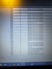
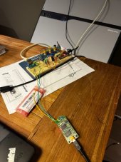
Found a nifty device called “USB Tin” on Amazon, which comes with a win app “USB Tin Viewer” which allows me to view data coming out of the inverter, confirming its pin 2-CanH, pin 3-CanL and 4-GND, so that part is also resolved. Still see nothing in the info part of the app, when connected like that, but could also be because key is missing; chip ID is 9629e748 I do see the ESP sending data on the CAN so confirm that also works. Awaiting further instruction. Thks MarcelHi Constantin, thanks for your reply. The data would be given I have a 16S Lifepo4 with 80Ah @ 51.2 nominal volt, the BMS @ 100A and the inverter does 75A @ 48 volt. Like with all things I like to keep, do not want to stress more than 80% / 90% hence:
Battery Voltage: 51.2 volt (3.2 per cell)
Charge Voltage: 57.6 volt (3.6 per cell)
Charge Amps: 60 A (75A x 80%)
Discharge Voltage: 45 volt (2.5 / 0.9) x 16
Discharge Amps: 60 A (75A x 80%)
Temperature: 45 Celsius.
Hope this is correct. As I wrote, I have not been able to verify the correct connection between the inverter and the ESP canbus. I was able to identify the pins with signal coming out of the inverter.
Thanks, Marcel
Last edited:
mrconstantin
New Member
46c755007bc2b40889bfbf1e6bbfdc56Hi
Very nice work !!, I try to test it on a Sunt inverter
My Chip ID eff9d108
Peter Laub
New Member
Wie melde ich mich für MQTT an.
Ist dies die richtige Plattform? HiveMQ Cloud Free-Plan
Ist dies die richtige Plattform? HiveMQ Cloud Free-Plan


