What kind of efficiency are you getting through that 12V supply?This is a 120W 12V LED supply operating on a 60V array to float charge a battery. They won't adjust up to 13.8V without a resistor modification, but to operate 12V equipment they are fine as they are. 120W and 180W are almost identical. You can not purchase over 180W because those use supplies use a voltage doubler circuit which will not work on DC. I never paid more than $10 for one shipped by waiting for an auction on ebay to go low bid. Upper left is the 120V 10A supply.
View attachment 167656


You are using an out of date browser. It may not display this or other websites correctly.
You should upgrade or use an alternative browser.
You should upgrade or use an alternative browser.
Charging a HV battery with 500w array
- Thread starter Block
- Start date
Good point. Only sun perfectly overhead can generate full power from all panels…The rails on your rack sticking up above the panels are going to kill PV output when they throw shadows on your panels.
I agree, aside from midday sun, unless ya park east/west, the rails will block panel production.The rails on your rack sticking up above the panels are going to kill PV output when they throw shadows on your panels.
efficientPV
Solar Addict
- Joined
- Sep 24, 2019
- Messages
- 1,371
I think they are around 85%, but that is only for a small section of voltage. The nice thing would be it only charges when the 120V battery when the 12V battery is near full, perfect diversion. The solar panels naturally limit current. What nobody discussed is sharing common NEG of both batteries. I doubt the 120V is tied to ground. Likely it floats. Charge controllers typically don't share a common PANEL NEG and BATTERY NEG.What kind of efficiency are you getting through that 12V supply?
Actually, isn’t it only charging the 12V battery with the first 120W of solar power (or first 141.2WDC assuming 85% efficiency)?I think they are around 85%, but that is only for a small section of voltage. The nice thing would be it only charges when the 120V battery when the 12V battery is near full, perfect diversion. The solar panels naturally limit current. What nobody discussed is sharing common NEG of both batteries. I doubt the 120V is tied to ground. Likely it floats. Charge controllers typically don't share a common PANEL NEG and BATTERY NEG.
If the solar is putting out 300WDC, 141.2WDC is used to charge the 12V battery @ 120WAC and the remaining 158.8WDC is used to charge the HV battery, right?
And once the 12V battery is full, 100% on incoming DC solar power is used to charge the HV battery, as you state.
What happens when the solar power is insufficient to power the 12V charger, let’s say 70WDC of incoming solar power, for example?
efficientPV
Solar Addict
- Joined
- Sep 24, 2019
- Messages
- 1,371
When the voltage to charge the battery, slightly over array power point + power supply, current flows. If the 12V battery still needs additional charge, the charger will find a new artificial power point voltage where it gets maximum power to the 12V battery. the 12V charger will always grab what ever power it can. As that eases off power is diverted to 120V battery as the result of array voltage climbing over power point. It is not precision, but a low tech and low cost way of doing it. My home systems work on this principal.
Hey everyone, thanks for the replies.
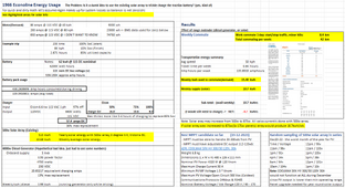
Here are some numbers on the load and PV stats. I made a spreadsheet from my BMS data and some solar calculators:

Notes from that sheet:

Option 1: It would be cool to make a custom MPPT like www.realsolarcars.com did with his Volt. I have no problem assembling a board, but designing one from the ground up seems like a bad idea, even with his schematics to work with.
Option 2: After doing more digging, there are some higher voltage MPPTS that might work with the system. These all seemed ideal:
This is where I'm at now if anyone has any input… Has anyone used the AERL inverter specifically?
Also, agreed on the rack possibly interfering with solar output. I can modify that in the future, but would like to get this science experiment working first.
Here are some numbers on the load and PV stats. I made a spreadsheet from my BMS data and some solar calculators:
Notes from that sheet:
- Weekly commute is 42km(26mi) driving across town. 133amps avg, 50km/hr(31mph) = 15.40kWh avg
- Weekly solar panel energy is 10.68kWh avg. This calculator factors my location, panel tilt (none), and some system losses. This is assuming the panels will always be unshaded, which is correct for home and work parking. Pvwatts is the site.
- These panels could produce 69% of the energy needed for my weekly commute. I’m skeptical about that, but even if the panels produced half the kWh, it would be pretty cool.
- Chucked a 4000w generator in the same spreadsheet, because a friend wanted to see. Ignore this, it’s dumb.
- Upgrading the panels to an 875w array (largest I can add without rebuilding the rack) would cover commuting and more. 18.7kWh/wk avg.
Option 1: It would be cool to make a custom MPPT like www.realsolarcars.com did with his Volt. I have no problem assembling a board, but designing one from the ground up seems like a bad idea, even with his schematics to work with.
Option 2: After doing more digging, there are some higher voltage MPPTS that might work with the system. These all seemed ideal:
- Charge Controllers | Residential | Northern Arizona Wind & Sun | NAZ Solar Electric
- High voltage 96V 120V 192V 240V 384V 50A 60A 80A 100A MPPT solar controller with parallel connectio
- Tanfon MPPT High Voltage solar controller_Other solar products_TANFON solar power system, solar panel inverter, solar home system factory
- buy High Voltage 384V Solar Charge Controller 100A 150A 200A MPPT Solar Charger Controller 360V,High Voltage 384V Solar Charge Controller 100A 150A 200A MPPT Solar Charger Controller 360V suppliers,manufacturers,factories
This is where I'm at now if anyone has any input… Has anyone used the AERL inverter specifically?
Also, agreed on the rack possibly interfering with solar output. I can modify that in the future, but would like to get this science experiment working first.
Attachments
GXMnow
Solar Wizard
- Joined
- Jul 17, 2020
- Messages
- 2,727
All of these charge controllers are the "Buck" type. They can only reduce the voltage from the solar array to the batteries. You need the VMP of your solar array to be at least 10 volts over your maximum battery voltage. Common "12 volt" RV solar panels like yours are about 18 volts in the real world, you need at least 7 in series. Can you fit an array that will do that? 2,000 watts of panels will still only make 16 amps of charge current, so you don't need a very high current MPPT controller.
I have seen a few boost type MPPT controllers, but they are very low power, just 10 to 15 amps on the input side, so even less once they step up the voltage, and the ones I am finding top out at just 72 volts.
I have seen a few boost type MPPT controllers, but they are very low power, just 10 to 15 amps on the input side, so even less once they step up the voltage, and the ones I am finding top out at just 72 volts.
Understood,
I can’t find any with boost and buck features, an inverter that can do both would be custom, or impossible? Yes, this could be less than 4amps max, still allegedly 10kWh per week.
While I’m asking the ultra-dumb questions…
I can’t find any with boost and buck features, an inverter that can do both would be custom, or impossible? Yes, this could be less than 4amps max, still allegedly 10kWh per week.
While I’m asking the ultra-dumb questions…
- I can find 60vdc to 120vdc dc/dc converters. Has anyone run one directly off an mppt controller (PV -> 60vmppt -> dc/dc step up -> 120v HV pack).
- Yes, I can upgrade the panels to about 875w max. Attached a sheet. A large array like this would give the AERL unit more uptime, but would still likely cut off during morning and evening.

- What is the possibility of splitting the pack in half, since there are TONS of 60v mppt inverters? It still needs to have a 120v output for the traction motor. Think I'd get weird shorts or transient voltage? Feels naughty.

Last edited:
GXMnow
Solar Wizard
- Joined
- Jul 17, 2020
- Messages
- 2,727
The way MPPT works, it is not easy to put another DC to DC converter in the line.
This is an odd thought, but it might work.
How about 3 panels to a boost converter charging 1/2 of the battery bank, and another 3 panels and a second boost converter charging the other half of the battery bank. Check out this charge controller.
You are at 35 S total, does that sound right? With 35 being an odd number, the systems would be 17S and 18S on the charge controllers. So you would need to be able to set the voltages to the proper bulk settings. I think this one can do that. The manual is quite vague though. For a 3.4 volt per cell charge, that would be 57.8 volts and 61.2 volts respectively. This is not really a true MPPT charge controller. It sort of works backwards. You also tell it the voltage you want on the solar panel. It will ramp up the current until the solar panel input voltage drops to that setting. I have not been able to find what the maximum input voltage is. Will it take your 3 panels in series??
This is not ideal as it is possible for one half to get more charging power than the other. You might want to interleave the solar panels so any shadows hopefully hits both arrays about the same amount. And make so you have a decent active balancer on the system as well. So 300 watts charging a 60 volt battery bank, but two systems in series. Also keep in mind, the common terminals all need to float as one common will be up at 60 volts.
I don't know if anyone makes a solid active balancer that works on that many cells. Most top out at 24 S. But could you use two 24 S balancers and have them overlap on the center 13 cells? This would allow the balancers to push power to a cell in the other half of the pack.
It would not be a totally cheap experiment.
zanydroid
Solar Wizard
You can also consider SolarEdge optimizers that are locked to have fixed output voltage. I believe this also turns off RSD and turns on IndOp (Independent operation, IE no need for SolarEdge inverter telling the optimizers what to do, so presumably they do the right magic to match current, but this gets into some pretty poorly documented territory). SolarEdge have boost converters inside.
There's at least two forum members that have bought and used these (not sure which store). Those two do not include me, I just like how devilish this approach to solar hacking is.
This is probably not the best store to buy it from, but it's the first one on Google. You can ask them to hard code any output voltage you want.
400bird
Solar Wizard
Genasun makes boost MPPT charge controllers. They are low power and they don't list anything outputting 120 VDC. But there's a spot on their website about reprogramming the unit for special purposes. You might contact them to see if they can crank it up to 11 I mean 120 volts. Then you could just run a few of them and have an easy route.
Unlikely, but it only costs a phone call or email to find out.
Unlikely, but it only costs a phone call or email to find out.
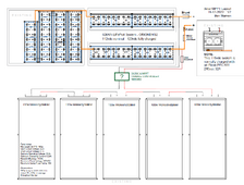
@GXMnow - I can split the pack exactly in half, since it’s 70 cells with sets of 2 paralleled. However I would be splitting one of the paralleled sets in the middle. Seems fine to me, knowing nuthin’. Mind checking the drawing in item #3 again, the green text specifically. OrionBMS2 actively balances up to 200mA, but only when the cells are above a settable “start balancing” voltage. Good tip on interweaving the solar panels, but do you think I could still get away with one 60v mppt in this arrangement? Simplified view:
@zanydroid - I hadn’t considered boost converters on the panel side, thanks. I have contacted them, but I can’t find anything at the exact specs needed. The forum members bought these to boost their panel voltage and reduce power loss from shading?
@400bird - Thanks, I just contacted them. Also contacted a few alibaba suppliers about possibly modifying a unit. I don’t think I can use just a boost converter, since the panel voltage rises above the battery voltage during the summer(?). Man, I built the worst system possible for solar.
yabert
Solar Enthusiast
You can find 128 cells solar panel who output around 75V nominal. So 2 panel for 150V will solve your problem.Their minimum PV voltage cutoff is “battery voltage +10vdc”, meaning these inverters won’t even turn on unless the panels are outputting 130vdc. I’ve barely measured 120vdc off the panels all winter.
The challenge will be to find small enough panels to fit your footprint.
Here one example: https://maxeon.com/us/sites/default..._470-485_1400mm_cable_dc_ds_en_ltr_548517.pdf
yabert
Solar Enthusiast
Oh! I realize that 64 cells solar panels (commonly call 40V panel) can fit the bill when 4 are hook in serie.
Many smaller watt/sizes are available.
Many smaller watt/sizes are available.
zanydroid
Solar Wizard
Boost panel voltage to deal with minimum string limit or to match current to existing string.I hadn’t considered boost converters on the panel side, thanks. I have contacted them, but I can’t find anything at the exact specs needed. The forum members bought these to boost their panel voltage and reduce power loss from shading?
Presumably you have normal panels so the input voltage and current are within limits of that SolarEdge module. You would look for the final voltage you want to achieve a voltage above the MPPT limit. And you would have one per panel.
Also it makes the output string voltage stiffer than the native panel but I don’t think you can readily use this unless you find a HVDC charger that can be set to a low current limit.
zanydroid
Solar Wizard
Is that common? I’ve heard of 66 and 72.Oh! I realize that 64 cells solar panels (commonly call 40V panel) can fit the bill when 4 are hook in serie.
Many smaller watt/sizes are available.
I thought factors of 6 were the most common.
Anyway you got 54, 60, 66, 72 in warehouses all over the world. Just need to make the math work. If you look hard you might be able to find double cuts that are wired to double the voltage for same footprint but I don’t think these are easy to find unless you are a panel shopping pro.
You can get to over 256 series cells with 5x 54 too. But I thought OP had a fixed amount of footprint and or existing panels, that is why I recommended dc optimizers since that is a way some people make lemonade from some situation where they are stuck with panels or very specific footprint they need to fit. Easier to hack in some MLPE than to custom cut some panels.
Well you can also custom cut panels by buying individual cells and connecting them yourself for the exact voltage. They are easy to buy and the instructions are out there. That has always felt like sweatshop work to me and it will be mechanically weaker than buying a panel.
Similar threads
- Replies
- 2
- Views
- 165
- Replies
- 77
- Views
- 3K
- Replies
- 7
- Views
- 884