diy solar

diy solar

Combiner Box Fuses and Breakers

Ddow

New Member
Joined
Mar 18, 2024
Messages
9
Location
Colorado
The more threads I read the more different ways and opinions there are. So if I could get some expert advise on my particular system I would appreciate it.

8 250W Panels (potentially very cold -10F)
4s2p
Vmp 18.9V
Voc 22.8V X 4 = 91.2 V
Imp 13.2A
Isc 13.7A X1.5 = 27.4A

2 X 4 panel arrays are 30' from entering the house. Once in the house (replacing a 12V system) there is a QO breaker box and the remainder of the run is 30' to the MPPT. The in house wire already is 1/0 and I would like to re-use this so that I don't need to pull new wire.

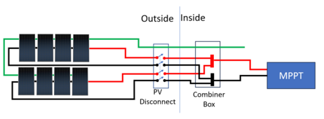
I am thinking of using 10awg to enter house and combining these arrays in this "combiner" box, before running on the 1/0 to the MPPT.

The box is presently a Square D QO. Can I put a SQ D 50amp (27.4X2) double pole breaker in here as a disconnect? I understand they are rated to 48V DC nominal but my voltage is much higher than this so I am thinking this is a bad idea as a disconnect?

So I am looking at using a Midnight Combiner box, MNPV6 150V , with two double pole 30amp breakers MNEPV30-600-2pp , so both arrays can be disconnected separately.

Panels need a 20amp fuse, "Max Series". Should this fuse be at the panels or can it be 30' later at the combiner box? I am thinking it doesn't matter? And if each 4 panel array has its own breaker do I still need these fuses?

Thanks for your suggestions or advice.
 
With only two strings, you do not need fuses at all, but you do need an 'accessable' disconnect. (In NEC terms, 'accessible' means 1st responders can get to it.)

1713305500886.png

Fuses or breakers are only needed when there are 3 or more strings.

However, you do have to size the wires correctly. The NEC requires them to be sized for 1.56x Isc.

  • Before the combiner box the wires must be sized for 1.56 x string Isc = 1.56 x Panel Isc = 1.56 x 13.7 = 21.372A
  • After the combiner box, the wires have to be sized for 1.56 x Array Isc = 1.56 x (2 x string Isc) = 1.56 x (2 x 13.7) = 42.74A.

You may want to review this resource:

 
My 4s panels have Isc 13.7X1.56= 21.4A
Max series fuse rating 20A
I get how I wouldn't need OCPD if the Isc was under 20A for my parallel strings, but because the Isc Amps are over 20 does the NEC say I should fuse each series?

I think a 30A breaker on each series then works as a disconnect and I would still need the fuse to provide OCP.

MNEPV30-600-2pp on the midnight site sends you to this data sheet https://www.midnitesolar.com/pdfs/CBI_YA_Datasheet_2023.pdf and it says these are Polarized.

"Do not use polarized breakers as over current protection devices on solar strings." on your suggested paper. Is this true even for double pole breaker? Can I use these for disconnect if the OCP is being provided by lower amp (20amp) fuses?
 
The max series fuse question is a good one. If we just add the two Iscs together, two strings are still under the 20A.

The NEC requires two 1.25 multipliers (That is where the 1.56 comes from). The first 1.25 multiplier is to cover any extra current due to the Isc only representing 'Standard Test Conditions'. They want to make sure the max current covers all conditions. The 2nd 1.25 multiplier is there to make sure the wire is large enough to withstand a continuous short circuit. If either of the multipliers are not used, the calculation remains under 20A. Technically, I think you are correct that string fuses (rated at 20A) are required. However, everyone I know stays with the rule of thumb that says 2 strings don't need the fuses. I don't think an inspector would question it either.

Where are you planning to put the 30A breakers?
The reason not to use polarized breakers is that for string OCPD the protection is for the other strings backfeeding current into the shorted strings. This creates a current that is opposit of the normal current. If you place the polarized OCPD in the direction of the normal current they will not protect from the backfeed. If you place the polarized OCPD in the direction of the backfeed, they can develop a sustained arc (and burn) if they are manually opend during normal operations.

If the 30A breakers are *after* the strings are combined, there is no possibility of backfeed so you can put them in the direction of normal current and used them as disconnects. (At 30A, they will never pop)
 
I am far from an expert on home solar, but in CA, we are required to have a rapid shut down system to kill off the solar panel voltage on the roof and at each panel.

So the setup has to disconnect each panel and short itself out so that firemen can flip a switch and safely spray water on the roof.

The typical setup feeds a 24 volt / 10 amp max "turn it on" signal up to the roof to power the relays up there. There are companies that sell these, although interestingly some of them are not rated for cold conditions.
The rapid shutdown requirement has been in the NEC since 2017(?). It is not just CA.

I don't know about 'shorting' the panels. I had not heard that before. I guess if the VOC is high enough on the panel it might be needed.


Most systems these days use a signal imposed on the power lines and 'receivers' at each panel. (There is no need to run a separate control wire) The transmitter is constantly sending a 'stay on' signal. If the signal ever goes away the receivers at each panel disconnects the panel. Tigo is probably the most common system for this. Many inverters these days have the transmitter built in.

Thank you.

So for instance in the OPs situation, if they wanted to have rapid shutdown per panel, would they put a TS4-A-O 700W on each panel for the rapid shut down part.

If the solar charge controller did not have the signal for keep alive - how would they get this signal up to the panels / controller?

If it were me, I would rather use a separate signal wire to avoid RF noise, as there is more than enough around here already. Is there a controller for a DC coupled setup that will work?

Let's assume that they don't feel the need for the cloud connect feature or don't want to connect the system to the internet.


Thanks

Harry
 
The max series fuse question is a good one. If we just add the two Iscs together, two strings are still under the 20A.

The NEC requires two 1.25 multipliers (That is where the 1.56 comes from). The first 1.25 multiplier is to cover any extra current due to the Isc only representing 'Standard Test Conditions'. They want to make sure the max current covers all conditions. The 2nd 1.25 multiplier is there to make sure the wire is large enough to withstand a continuous short circuit. If either of the multipliers are not used, the calculation remains under 20A. Technically, I think you are correct that string fuses (rated at 20A) are required. However, everyone I know stays with the rule of thumb that says 2 strings don't need the fuses. I don't think an inspector would question it either.

Where are you planning to put the 30A breakers?
The reason not to use polarized breakers is that for string OCPD the protection is for the other strings backfeeding current into the shorted strings. This creates a current that is opposit of the normal current. If you place the polarized OCPD in the direction of the normal current they will not protect from the backfeed. If you place the polarized OCPD in the direction of the backfeed, they can develop a sustained arc (and burn) if they are manually opend during normal operations.

If the 30A breakers are *after* the strings are combined, there is no possibility of backfeed so you can put them in the direction of normal current and used them as disconnects. (At 30A, they will never pop)
Thank you this was helpful. I will combine 4s2p before disconnect. However the Isc is now 42.8 so will use 50amp for the disconnect breaker. Does that sound correct? Then run 8awg into house.

Panels are not on the roof. Should this disconnect be outside or can it be inside?
 
If it were me, I would rather use a separate signal wire to avoid RF noise, as there is more than enough around here already. Is there a controller for a DC coupled setup that will work?
They might exist, but I don't know of any

Let's assume that they don't feel the need for the cloud connect feature or don't want to connect the system to the internet.
Tigo sells two systems. One is just the rapid shutdown system and the other is an optimizer system that will also do the rapid shutdown. (The Cloud Connect is for the optimizer system that has the cloud internet connect)

The rapid shutdown system uses this transmitter:

The transmitter talks to their receivers. (TS4-A-F (add-on), TS4-A-2F (add-on for two modules)
 
Thank you this was helpful. I will combine 4s2p before disconnect. However the Isc is now 42.8 so will use 50amp for the disconnect breaker. Does that sound correct? Then run 8awg into house.
That sounds correct.

Should this disconnect be outside or can it be inside?
To be code complaint it should be outside.
 
Back
Top