You are using an out of date browser. It may not display this or other websites correctly.
You should upgrade or use an alternative browser.
You should upgrade or use an alternative browser.
Combiner box issues
- Thread starter clint0n
- Start date
clint0n
New Member
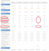
Max pv voltage is 145v for that built in mppt
"Max DC voltage 270 V"
Plenty of headroom there.
Bridge rectifier, 100A. Maybe heatsinked to box. Probably not a problem for the current. But I don't see the point to using it.
That would certainly explain things. But the chart says MPPT range up to 145V. Max 270V.
Are the strings still putting out 160V WHILE you get next to nothing at the inverter?
If so, there is an open circuit. use volt meter to find out where 158V is being dropped.
But if the strings drop from 160V to 2V when breaker closed, then there is a short (likely at the inverter.
Brett V
Mad Scientist
clint0n
New Member
So if the mppt shorted, will it be as simple as replacing a fuse in the inverter?
wpns
Solar Joules are catch and release
Um, no. First, there’s no ‘fuse in the inverter’ that, if blown, would cause the MPPT input to be shorted out.So if the mppt shorted, will it be as simple as replacing a fuse in the inverter?
Second, if the MPPT input is shorted out, there are dead semiconductors.
Third, if you exceeded the max string input voltage, it’s not surprising that the MPPT input shorted out, and if you repair it, it’ll blow up again.
seneysolar
Solar Addict
IF voltage exceeded the max input for the mppt. Unfortunately it may be toast. This is generally a never exceed value.So if the mppt shorted, will it be as simple as replacing a fuse in the inverter?
As a bandaid, you may be able to use a stand alone mppt to your batteries if your inverter functions normally from the batteries. You just dont have a "built in" CC anymore.
clint0n
New Member
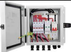
So get rid of the mds and get bus barsThis photo gives you a basic idea of how it should be wired using the components you have. View attachment 213925
Entire system was designed by an "engineer " in China, sold as a turn key system. So I guess I should be reaching out to them before I void the warranty opening up the inverter. Thanks for the help.IF voltage exceeded the max input for the mppt. Unfortunately it may be toast. This is generally a never exceed value.
As a bandaid, you may be able to use a stand alone mppt to your batteries if your inverter functions normally from the batteries. You just dont have a "built in" CC anymore.
seneysolar
Solar Addict
To be clear, Im not recommending that you open up the inverter to fix anything. If your charge controller is indeed damaged, one option is simply using a stand alone, separate charge controller to charge your batteries and abandon the built in one, assuming the rest of the inverter is ok.So get rid of the mds and get bus bars
Entire system was designed by an "engineer " in China, sold as a turn key system. So I guess I should be reaching out to them before I void the warranty opening up the inverter. Thanks for the help.
I do think its worth verifying the max mppt input voltage, 145v seems low. It could be just fine with a much higher voc limit. Its not uncommon for Chinese manuals to get mis-translated when selling products in multiple countries.
Last edited:
Hedges
I See Electromagnetic Fields!
- Joined
- Mar 28, 2020
- Messages
- 21,197
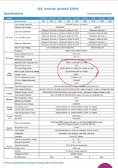
This is the pdf download spec sheet. Max pv open circuit voltage says 145?
Im not seeing 270 for DC? Thats max AC input i think.
View attachment 213923
You're right - spec sheet linked on the page says 145V.
The page itself said 270V for "DC"

clint0n
New Member
clint0n
New Member
If I disconnect the pv in from the inverter and the lines read 2v still, would that not mean the issue was in the combiner box, not the inverter, and that not enough power is making it to the inverter for it to recognize input?
seneysolar
Solar Addict
Most likely yes.If I disconnect the pv in from the inverter and the lines read 2v still, would that not mean the issue was in the combiner box, not the inverter, and that not enough power is making it to the inverter for it to recognize input?
clint0n
New Member
Looks like I'm not that lucky, is the internal charge controllerMost likely yes.
seneysolar
Solar Addict
ShootLooks like I'm not that lucky, is the internal charge controller
clint0n
New Member
Thanks for all your help though.Shoot
clint0n
New Member
You'd think there would be a circuit breaker on the pv input like the ac in and out. Guess I'm off to find one that can handle upto 175v pv max inputThanks for all your help though.
seneysolar
Solar Addict
Circuit breakers only control current, not voltage.You'd think there would be a circuit breaker on the pv input like the ac in and out. Guess I'm off to find one that can handle upto 175v pv max input
Limited MPPT is one of the reasons I don't like the "all in one" units. The price is usually the only attractive feature. I prefer an Inverter/charger + separate MPPT.
For string voltages of 160, I would look at something like the Midnite Classic 200 charge controller. You always want to give yourself plenty of headroom on the max PV input voltage. Or you need to reconfigure your panel strings, one less panel per string.
clint0n
New Member
Thanks again.
Hedges
I See Electromagnetic Fields!
- Joined
- Mar 28, 2020
- Messages
- 21,197
But if the inverters max pv input is 145vdc I don't get why it was functioning at 160vdc for weeks.
Because they aren't guaranteed to fail at 146V. They are guaranteed to work at 145V.
When running at a time of peak power, things got hotter. This makes transistors and capacitors more likely to fail with over-voltage.
There is DC bias, plus there is ripple current which heats capacitors, and increases heating of transistors.
clint0n
New Member
Thanks.
Similar threads
- Replies
- 20
- Views
- 1K
- Replies
- 4
- Views
- 281
- Replies
- 10
- Views
- 371


