diy solar

diy solar

Critique please

To summarize the above.
Lets say your inverter and dc_fuse block can pull 300 amps.
Up to 50 amps could come from the dc2dc_charger and the balance will come from the battery.
If nothing comes from the dc2dc_charger then all current must come from the battery.
300 amps out means 300 amps in.
Wow, thank you, that's a lot of info and we will go over it all and let you take a look. Working on kitchen cabinets now. Once again much appreciated.
 
I'm not talking about the MRBF block at all. But since you brought it up, in my opinion, you should be using a Class T fuse immediately downstream of the battery, not an MRBF.
I know I didn't mention but, just above the battery is a breaker for the solar, I just haven't hooked the out cables to charge controller, we will take all info into our rebuild. Thank you
 
I know I didn't mention but, just above the battery is a breaker for the solar, I just haven't hooked the out cables to charge controller, we will take all info into our rebuild. Thank you

Sounds good. Don't take the constructive criticism the wrong way. We want to make sure your build doesn't end up as a thread in the "Up In Smoke" subforum. A safe build may not be inexpensive, but it will keep your system from letting the smoke out.

I went through the same thing when I put my plan out there for constructive criticism. It helped me a lot and I still got at least one thing wrong that I had to change after the system was in place.
No no I put it out there because I want my wife and I and dog to be safe. I love construction criticism. Sometimes the written word gets taken the wrong way. ? All very much appreciated.
 
From left to right...

Do those batteries have a smart BMS?
If not you probably want to add a shunt.
Yes, I did forget the shunt, but I have one available.
Your inverter alone can pull ~240 amps from those batteries and they are only rated for 200 continous amps aggregate.
Add the dc fuse block loads to that number and its too high for the batteries.
The only thing running off the inverter would be the water heater with 1440 W. The fuse block is well under 50. We bought the 2000W inverter to have for the future if upgrade is needed.
Would we be ok for our current scenario with our 200 Amp Battery bank?
Rotate the battery pack 180 degrees
That way the battery terminals line up with the inverter terminals
We can certainly do this but what is the reasoning behind it? We are new to all of this and trying to make sense out of it
The amp ratings for the busbar is in continuous amps
The busbar is rated for 300 amps continuous
300 amps continuous / .8 fuse headroom = 375 fuse_block amps

Each fused branch position is rated for 240 amps continuous
240 amps continuous / .8 fuse headroom = 300 fuse amps
We were not aware that the 240 continuous amps can run thru EACH of the branch positions. We thought that the fuses on the branches combined could not exceed 300 amps. (we thought 200 A inverter fuse plus 80 A fuse box was just under 300 A and therefore did not add the charge controller to the bar) Thank you for the learning experience.
2000 ac watts / .85 conversion factor / 10 volts low cutoff = 235.294117647 continuous inverter amps

300 busbar amps - 235.294117647 inverter amps = 64.705882353 continuous fuse_block amps

You can fuse the fuse block feeder circuit as high as 75 amps with 6 awg wire
We are running 4 awg with 80 amp fuse for the fuse box. So we should be fine.
You should fuse the inverter circuit at 250 amps with 2/0 wire
You can fuse the dc2dc charger as high 60 amps with 6 awg wire.
We are using 60 amp fuse with 4awg wire.
You can fuse the wire from the starter_battery as high as 80 amps with 6 awg wire.
Put the fuse at the starter battery end of the wire.
We have it fused with a 60 amp at the starter battery end with 4 awg wire.
Move the disconnect switch to the fuse_block feeder circuit.
will do.
I would like to congratulate you on the selection of the blue sea 5196, its very well suited to the application.
Hope the negative busbar is similarly rated and similar quality.
It is indeed, it is a bluesea 250 amp

I just thought about an issue with my negative connections. I was wondering if I could connect the negative from the starter battery to the negative of the solar controller and then run from there to the common negative busbar? What are your thoughts?
Right now I have it connected directly to the busbar but I do not have any position left to connect negative from the solar controller to the busbar as well.
Thank you for your time and input.
 
On your bus bar, it's OK to stack lugs on a stud. I think the recommendation is no more than three on a stud. I would stack the lugs associated with low charge/discharge items.
 
The only thing running off the inverter would be the water heater with 1440 W. The fuse block is well under 50. We bought the 2000W inverter to have for the future if upgrade is needed.
Would we be ok for our current scenario with our 200 Amp Battery bank?
1440 ac watts / .85 conversion factor / 10 volts low cutoff = 169.411764706 inverter amps.
Its unlikely that you are going to run all your dc loads at the same time so it should be fine.
We can certainly do this but what is the reasoning behind it? We are new to all of this and trying to make sense out of it
The positive battery terminal will be fairly directly inline with the inverter positive terminal same for the negatives.
That will keep your high amperage lines from crossing at oblique angles and causing weird magnetic induction effects.
It should also make for a tidier layout.
Also the negative lines are at the same voltage as the van chassis.
The positive lines will be closer to the wall and slightly more protected.
It is indeed, it is a bluesea 250 amp
Should be fine.
I just thought about an issue with my negative connections. I was wondering if I could connect the negative from the starter battery to the negative of the solar controller and then run from there to the common negative busbar? What are your thoughts?
I would connect the starter battery negative to the negative busbar.
The dc2dc charger "common" can also be connected to the negative busbar.
You can stack these lugs, starter battery on the bottom and dc2dc charger on the top.
The pv negative can go to the negative busbar, dc2dc charger "common" or to a fuse_block negative branch position, whichever is easier.
Right now I have it connected directly to the busbar but I do not have any position left to connect negative from the solar controller to the busbar as well.
Thank you for your time and input.
You are most welcome.
 
Last edited:
1440 ac watts / .85 conversion factor / 10 volts low cutoff = 169.411764706 inverter amps.
Its unlikely that you are going to run all your dc loads at the same time so it should be fine.

The positive battery terminal will be fairly directly inline with the inverter positive terminal same for the negatives.
That will keep your high amperage lines from crossing at oblique angles and causing weird magnetic induction effects.
It should also make for a tidier layout.
Also the negative lines are at the same voltage as the van chassis.
The positive lines will be closer to the wall and slightly more protected.

Should be fine.

I would connect the starter battery negative to the negative busbar.
The dc2dc charger "common" can also be connected to the negative busbar.
You can stack these lugs, starter battery on the bottom and dc2dc charger on the top.
The pv negative can go to the negative busbar, dc2dc charger "common" or to a fuse_block negative branch position, whichever is easier.

You are most welcome.
Hello John Frum:
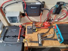
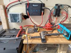
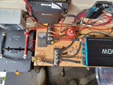
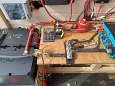
Do you mind taking a look at our revamped (hopefully final) electrical system in our van.
We are using two 100 A Renegy Lithium Smart Batteries.
We are using a 250Amp fuse at the battery, a 250 A to the inverter, 60A fuse going to fuse box, 60 A going to the solar controller, 60 A coming from van battery to solar controller via 4 AWG.
2/0 on battery and to inverter.
shut off switch going from 60 A fuse to fuse box
Nothing has been fully tightened yet.
What do you20230301_120656_resized.jpg20230301_120703_resized.jpg20230301_120714_resized.jpg20230301_120733_resized.jpg think?
Thank you kindly for your time.
 
Looks good as far as I can tell.
Where does the wire from the negative busbar that disappears into the table top go?
Also where does the wire from the dc2dc charger common disappear to?
What size is the main wire and what size is the main fuse?
 
The small gauge red wire for powering the Shunt electronics should have small in line fuse, 1A fuse should be enough to protect that wire from catching on fire if the Shunt's electronics shorted out.
 
Looks good as far as I can tell.
Where does the wire from the negative busbar that disappears into the table top go?
Also where does the wire from the dc2dc charger common disappear to?
I routed it under the table top to avoid the wires from crossing. It goes to the solar controller negative.
What size is the main wire and what size is the main fuse?
That's 2/0 on the battery, from main battery fuse to positive fuse block is 2/0, and also 2/0 to the inverter
negative is 2/0 to the shunt to the bus bar and 2/0 to the inverter
everything else is 4 AWG
solar cables are 10 AWG
main fuse on battery is 250A
 
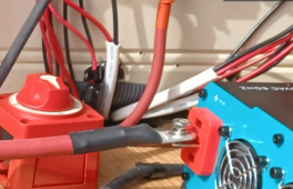
BTW, please check the Red inverter terminal, it looks like it is not tightened. You should also do pre-charge the capacity bank in the inverter so it will not trip BMS over current circuit.
1678066744550.png
 
Last edited:
suggest you stress test to max draw from full battery to empty.
Check all the joints for excess heat.
 
Back
Top