diy solar

diy solar

Design sketch (DC side)

oc_geek

learning off-grid solar
Joined
Apr 1, 2023
Messages
19
Location
ITALY
Hi,
recently joined this wonderful forum :)
I've spent some time already reading threads on the subject, the very useful filterguy's guides and Victron's "Wiring Unlimited"..

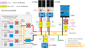
i've made a sketch of my plan for the DC side for my project.
While i was initially thinking to use MCCB(s) on the battery side, in the likes of what Andy (offgridgarage) does
i've then changed my mind.. mainly due to the high resistance those devices introduce.. which is gonna consume lot of W and create heat on the path

However here is my current sketch of the DC side and i indeed welcome any feedback exp if something doesn't look as it should
( i didn't include wires sections cse the drawing was already crowded enough..)

I'll likely start with one battery bank and add the others relatively after

Thanks
1681586344453.png
 
I saw one problem. The earth ground that is next to shunt - MUST be on the load side of the shunt. You already have one on your main negative bar - so I think the one by the shunt just needs deleted.

What could happen is some loads could use both grounds to bypass the shunt thus throwing off the shunt’s calculations.

I assume this is for an RV type unit. And you are using a mppt to convert the 48v to 12v. Do you need a 70a mppt for that? Do you start a generator or have hydraulic jacks?

Good Luck with the project.
 
I don’t see the specifics of the combiner.

Also confused about why on the DC load side there is a 20 amp fuse with a 100/75 SCC next to it?

-In addition to the fuses you have on each battery, I put an additional fuse after combined. 200 amps from a battery will provide 9.6 kw of power, more than the 6 kw inverter and DC loads will use. You probably have a limit you’ve designed it for, perhaps 400 amps after combined. Three batteries could push 600 amps of power no problem, but the system does not seem to need that much at 6 kw of power.
 
I saw one problem. The earth ground that is next to shunt - MUST be on the load side of the shunt. You already have one on your main negative bar - so I think the one by the shunt just needs deleted.

What could happen is some loads could use both grounds to bypass the shunt thus throwing off the shunt’s calculations.

I assume this is for an RV type unit. And you are using a mppt to convert the 48v to 12v. Do you need a 70a mppt for that? Do you start a generator or have hydraulic jacks?

Good Luck with the project.

Ok thanks, will remove the one on the Batteries Bus Bar

Sorry for the confusion on the DC load side i just reused the picture. That's gonna be a DC/DC converter not an MPPT indeed

Thanks
 
I don’t see the specifics of the combiner.
Are you ref to the Batteries bus bar ? That's a 30x10 section copper bar in the plans

Also confused about why on the DC load side there is a 20 amp fuse with a 100/75 SCC next to it?
I reused the MPPT picture (sorry for confusion) but that is a DC/DC converter for DC loads

-In addition to the fuses you have on each battery, I put an additional fuse after combined. 200 amps from a battery will provide 9.6 kw of power, more than the 6 kw inverter and DC loads will use. You probably have a limit you’ve designed it for, perhaps 400 amps after combined. Three batteries could push 600 amps of power no problem, but the system does not seem to need that much at 6 kw of power.
Each battery can potentially run alone (e.g. at the begin there will be only one)
Planned current draw is ~ 160 A overall; i have considered 0.8 fuse headroom factor so that's driving to the ~200A fuse(s)
There is indeed more power in the batterie(s) than the draw but that is intentional design (e.g. to overcome rainy days)
I also have a fuse prior to the inverter. Why an additional fuse after battery combiner ?

thanks
 
If I have a 3000w inverter, can I get by with a 100amp t class fuse on each battery?
 
Yes it will, provided wiring will tolerate. Perhaps 1 AWG wire depending on insulation.

Although 100 amp fuse would work, each battery is unlikely to push that much. I don't see 100 amps, about 4800 watts at 48 volts, being pushed to a 3000 watt inverter.

Unfortunately last year when I looked, I could not find a high AIC fuse for a 48 volt system for batteries less than 110 amps. I'm sure its out there, I just don't know what type that is.
how high do you need? Cooper Bussmann has ANN fuses that go below 100a


Interrupting Rating: 2,500A ac, 2,700A dc
 
EDIT: I se enow this could work. Rated to 90 VDC as low as 80 amps. Actual AIC needed for a 25 ah 48 VDC bank is anyone's guess
=================
Appears that fuse goes to 90 amps. would be nice to have them at 20 amps or 40 amps rated for Main Battery Protect.

I have a small less than 1000 watt inverter I was thinking of going 48 volts with, which is only around 20 amps, but I could find no 20 amp fuse, so I went with 40 amp fuse for a 24 volt system.
 
Back
Top