diy solar

diy solar

EG4 6000 EX blew Up

dareggaemon

New Member
Joined
Nov 10, 2022
Messages
20
I have now Idea why my system blew up. I have two EG4 6000ex split phase inverters I am trying to parallel. I had been running on one inverter for a few weeks. after receiving the second one I connected it via the manual and it made a loud pop and displayed error code 09. I contacted technical support and they found no error in my setup and provided me a replacement. I verified that both inverters were connected per the manual, confirmed both inverters were on the the software and I bypassed the neutral bonding which I did not do the first time because I'm grounded at the service panel and it still blew up as soon as I turned it on. However, second inverter blow the mosfets and the 1st inverter lost one of the AC output legs.

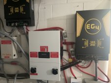
Help please. I don't know why it does not work. Please see below picture of my setup. the off-grid inverts are the eg4 6000ex inverters. the one on the left is the one that blew the mosfets and the one on the right lost one of the AC output legs. Each inverter has its own output and input breakers. The Grid-Tie inverter is its own separate system that only connects to the main panel. Both inverters had the same settings with setting 28 set to Parallel, and I even watched the signature solar videos and turned the inverters on in the same order they did on the video.
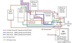
Wire Diagram.png
 
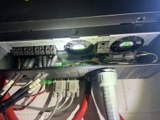
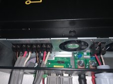
The first time the mosfets blew I had solar going to only one eg4 6000ex inverter at S8P3. On the second attempt I moved moved one string of solar panels to the second inverter for S8P2 and S8P1.

See DC connections below for both inverters.

  • On the inverter I got first I used 6 awg for all the AC connections. The solar panel arrays are ran 12 awg to to combiner and 10 awg from the combiner to the inverter. S8P2 (296V & 17A)
  • On the second Inverter I used 8 awg wire for all the AC connections. The solar panel array is one string 12 awg all the way. S8P1 (296V & 8.5A)

IMG_4916.jpgIMG_4913.jpg
 
The first time the mosfets blew I had solar going to only one eg4 6000ex inverter at S8P3. On the second attempt I moved moved one string of solar panels to the second inverter for S8P2 and S8P1.

See DC connections below for both inverters.

  • On the inverter I got first I used 6 awg for all the AC connections. The solar panel arrays are ran 12 awg to to combiner and 10 awg from the combiner to the inverter. S8P2 (296V & 17A)
  • On the second Inverter I used 8 awg wire for all the AC connections. The solar panel array is one string 12 awg all the way. S8P1 (296V & 8.5A)

View attachment 156551View attachment 156549
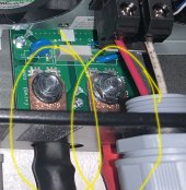
Is that correct? Edit...it was just different color heat shrink. Issue was located in the critical load/combiner panel for the AC output.
IMG_4913.jpg.
 
Last edited:
Is that correct? View attachment 156555

Edit: You won't be the last to swap the polarity.
I ran out of cable and had to use the black heat shrink cable for positive. I tested the battery and solar connections for polarity three times before connecting the inverters. I have been running one inverter by itself for two weeks while I waited for the other one to arrive.
 
I ran out of cable and had to use the black heat shrink cable for positive. I tested the battery and solar connections for polarity three times before connecting the inverters. I have been running one inverter by itself for two weeks while I waited for the other one to arrive.
Obviously something is wrong but it's not so obvious what that something is. I don't know that it would cause this problem but is it possible you have L1 and L2 crossed between the two inverters? It's going to be hard for us to determine that just from pictures.
 
I ran out of cable and had to use the black heat shrink cable for positive.
I'm still confused, you used black heat shrink for positive because you ran out, that makes sense; I would have at least wrapped it with red electrical tape or hit it with a red marker. So why is red heat shrink on the negative?
I tested the battery and solar connections for polarity three times before connecting the inverters.
Would you quadruple check the battery?
I have been running one inverter by itself for two weeks while I waited for the other one to arrive.
And you are 110% certain the wiring is correct? I have had read of issues with these running in parallel but I thought they were resolved.
 
I ran out of cable and had to use the black heat shrink cable for positive. I tested the battery and solar connections for polarity three times before connecting the inverters. I have been running one inverter by itself for two weeks while I waited for the other one to arrive.
Ok,

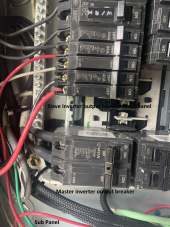
1st. take a photo of both AC breaker from the main panel and subpanel. Need to see both feeds are on the correct leg. Specifically looking for red and black coming out of the main and again entering the inverters and loads going from inverter to subpanel.

2nd. Label your wires. Get tape from a local hardware store. White, red, green and black.

3rd. Take a photo of the breaker and wires in your subpanel.

I ran out of cable and had to use the black heat shrink cable for positive.
4th. Ok, Why did you use red heat shrink on the negative

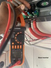
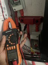
5th. While you are at it post some photos with your multimeter measuring DC Voltage and polarity. I've seen multimeters in the past that don't show polarity when reading DC...can you verify that your meter can read negative polarity?
 
Last edited:
I ran out of cable and had to use the black heat shrink cable for positive. I tested the battery and solar connections for polarity three times before connecting the inverters. I have been running one inverter by itself for two weeks while I waited for the other one to arrive.
I looked at your photos, in first photo all the wires are black without any identification such as white tape wrap to indicate neutral and red tape to indicate one leg from the other.

Most likely the wires there are swapped.
 
Those switches are not designed for 48Vw
Good eye, Thanks.
I was recently made aware of that in other threads I've read.
They will be upgraded hopefully sooner than later when I choose a new inverter...
They were never intended to be switched under heavy load, I added them as means to isolate packs only after disconnecting loads.
They have been working great since October and felt they were better than the really cheap clones on amazon.
Get the breaker Tim uses.

I have a big ABB shunt trip when I need to kill battery power. I did not install breakers for each battery, just a T fuse off each one with a solid busbar to the main busbar for the positive and a cable on the negative. Disconnecting one battery would require me to remove the Batrium K9 from the string anyway so having to power down and disconnect the negative isn't a big problem for me.
 
When it comes to 240vac I use black,red,white and green wires because I’m old, don’t need more confusion ? and there’s no chance it got swapped.
 
I'm still confused, you used black heat shrink for positive because you ran out, that makes sense; I would have at least wrapped it with red electrical tape or hit it with a red marker. So why is red heat shrink on the negative?

Would you quadruple check the battery?

And you are 110% certain the wiring is correct? I have had read of issues with these running in parallel but I thought they were resolved.
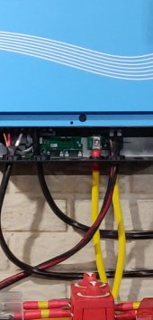
I ran out of heat shrink and wire. Initially I only had one inverter. I bought red battery cable and used it for both positive and negative to the inverter. I then got a second inverter and cut the battery cables shorter to reach both inverters.


The battery connections to the inverters are via a negative and positive busbar. I added 150 amp breakers between each inverter's positive connection between the inverters and busbar, and a 200amp breaker between the battery positive and the positive busbar.
IMG_4813.jpg+IMG_4918.jpg

I did some research on paralleling inverters and made sure both AC L1 output to the same leg on the sub panel when I was connecting them and vise versa with the L2 output. I'll have to get some red tape to make it easier to see in the future. but I retraced each wire and verified that they are on the same leg in the sub panel. 1688918956925.png

I also made sure to match the AC inputs as well. Although maybe its a case of me overthinking it. I have wired 3 other systems are are working fine but this is my first time doing parallel. I wish I had went with the 6500. Please see my picture below that shows my multimeter can read negative voltage.

IMG_4920.jpg
 

Attachments

  • IMG_4790.jpg
    IMG_4790.jpg
    245.5 KB · Views: 4
When it comes to 240vac I use black,red,white and green wires because I’m old, don’t need more confusion ? and there’s no chance it got swapped.
I admit that would be easier. I used the wire that I had on hand. I spent 30 minutes on the phone with signature solar testing each connection to make sure it was wired correctly. I even sent them pictures and videos and they found nothing wrong with the connections. I couldn't find any videos online of someone wiring these in parallel.
 
I'm still confused, you used black heat shrink for positive because you ran out, that makes sense; I would have at least wrapped it with red electrical tape or hit it with a red marker. So why is red heat shrink on the negative?

Would you quadruple check the battery?

And you are 110% certain the wiring is correct? I have had read of issues with these running in parallel but I thought they were resolved.
You would totally fail an inspection by an electrician, town, or insurance agent. Get a certified electrician to redo your cabling to meet local code, which will also most likely fix your problem.
 
The breaker for the slave input is the size of one space. Good chance it i only on one side of the panel.
It's a dual pole mini breaker and the subpanel will allow regular and mini breakers. I tested both inverters individually before trying to parallel them. also tested to make sure that each leg of the mini breaker was outputting 120v. The mini breaker was able to provide the necessary power to charge my car at 240v and keep my lights on at 120v.
 
Back
Top