diy solar

diy solar

EG4 Lifepower4 in parallel without rack

niteraven78

New Member
Joined
Sep 5, 2022
Messages
19
Hi all, first post here. How do I connect these in parallel without rack? The manual states:

WARNING: Do NOT parallel batteries by using jumper wires on the terminals. This will cause
high amperage in the final jumpers and potentially excessive amperage on the battery terminals.

Can I use a busbar? I see a bunch on Amazon with 4 terminals. I'll probably start with 1 battery and maybe end up with 2-3.

This is for a solar carport with low amps. Thank you.

Cheers,
Kyle
 
If I had 3 batteries I would hook the 3 + to one busbar and the 4th to the inverter? Same for - Is it the easy?
 
WARNING: Do NOT parallel batteries by using jumper wires on the terminals. This will cause
high amperage in the final jumpers and potentially excessive amperage on the battery terminals.

Can I use a busbar?
The Racks all use bus bars (as far as I know) can't see any reason not to go that way.
I use fuses between each battery and the bus-bar, then (bigger) fuses between the bus and the inverter(s) with DC rated disconnect.
 
Thank you for the response. I do not have room for a rack in my outdoor carport. I will be be building an elevated wood closed cabinet. The batteries will sit on their back and keep the enclosure slim.
 
Thank you for the response. I do not have room for a rack in my outdoor carport. I will be be building an elevated wood closed cabinet. The batteries will sit on their back and keep the enclosure slim.
If you apply the same type of connections, as described above, using fusing and bus bars, like the factory racks do, then you are re-creating the same protections.
The note you showed about "not parallel connecting with jumpers", i suspect is about not jumpering all the batteries together, and then connecting from Battery A to the inverter, with the others (battery B, C, D) all jumpered to battery A. This will cause problems, most notably that battery D will never carry it's share of the loads, and battery A will do most of the work, all the time.
One method to deal with this, jumper A to B to C to D
Then pos from A to inverter, and neg from D to inverter. This does balance the battery use better, however not as well as proper bus bars will with:
Battery A to bus, B to Bus, C to Bus, D to bus, and then pos bus to inverter, neg bus to inverter.
hope this helps.
 
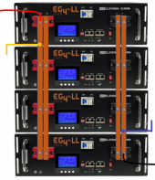
I see an issue, if you ever want to remove one rack,for any reason, then you have to remove all the bars, and you are offline.
The reason the factory cabinets have the bus bars mounted to the sides, out of the way for access to each rack.
I hope the bars will be coated, since it would be a huge safely issue having exposed bus bars right out front, and spinning a wrench in one hand...
 
I do not have room for a rack in my outdoor carport.
If you watch the vid, around 5:00 you see the SOK's connected all with just cables - no bus bars, then the main POS is attached to the top left battery, and the main NEG attached to the bottom right side, this is to assist with keeping all the batteries in a balanced state during use and charging.
When I had only two rack batteries, I stood them upright, i think like you are describing, they took less space this way, and work fine, as long as you keep out dust and dirt (water?) from going into the comms ports. If you have 4 racks, they may as well go flat stacked, since standing them up takes the same floor space, at lease mine did.
 
I see an issue, if you ever want to remove one rack,for any reason, then you have to remove all the bars, and you are offline.
The reason the factory cabinets have the bus bars mounted to the sides, out of the way for access to each rack.
I hope the bars will be coated, since it would be a huge safely issue having exposed bus bars right out front, and spinning a wrench in one hand...
I am going to have three columns, so two banks would still be in use.

Between terminals I plan on covering bars with heat-shrink tubing.
 
You have given me given me some good things to think about. Not sure I understand why A will carry more load vs D. Seems like the busbar would carry and balance the electrons equally.
 
Nevermind I reread what you said, busbar should work fine. Using cables (jumper to jumper) could cause an imbalance.
There is a good explaination on WindyNation's website, they show wire set up diagram the effects, how to balance.
Look up Windynation.com - how to configure battery bank.
 
Back
Top