diy solar

diy solar

Hello?My 12v setup

The batteries are in parallel. They each have internal resistance.
All that matters regarding wiring is for each battery to be in series with the same wire resistance. Doesn't matter at all how much of that series resistance is connected to positive terminal vs. negative terminal. Therefore individual wire lengths don't matter, just total positive plus negative length.
So, you are saying all cables need to be all the same length in my situation? (parallel)
But not in series?
 
Your approach looked fine to me. You had a range of cable lengths due to physical placement, but each battery had (approximately) same total wire length. And your wires are shorter (better) than the approach of making wires same length.

If you had connected all four batteries in series for 48V (assuming BMS tolerates that), no wire lengths would have mattered at all (for matching.) Only that more resistance is more loss and voltage drop.

There is another scheme to connect multiple batteries, number being a power of 2. Some wires carry the current of one battery, some carry the current of 2, pairs of wires get matched length, overall is perfectly balanced.
 
Another note, you can't stack more than 2 lugs on one post and ideally each lug has its own post which would you need to get 8 lug buss bars or more 4 lug ones and string them together. I like neat so I would get new buss bars.

And it looks like you are using a hammer style crimper. Opinions differ but I would switch to a hydraulic crimper. And if you get one spend the money to get the temco like this. It has plus sized dies and the standard sized dies have the awg size in them so the imprint it into the metal. And use quality lugs. And if you crimp and end up with wings there is an issue, bad lugs (thin metal), wrong sized wire (undersized), or wrong die used.


The cheap $40 on amazon like the amzcnc brand are harbor freight quality and the dies are generally metric but marked in awg. Makes wings even with the correctly marked dies. No imprints on most. Not good quality machining.
 
Not sure how many amps those busbars are really good for. Some are small, some are brass not copper.

Could put two lugs at one end of busbar, two at other end. Inverter in the middle. Half the current through the busbar.

My busbars are an air bridge, only held at the ends. I put one lug on top, one on the bottom, bolt through. Could do 4 lugs on one bolt that way, but I put two lugs at each end.

I'm gonna get me one of those good crimpers some day. Want to do some 4/0 cables.
I've been using a cheap Harbor Freight crimper. I think the 2/0 die works pretty well for 4 awg terminals, if I rotate after partially crimping to avoid making thin wings.
 
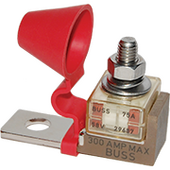
Looks like that "block" is the fuse holder that mounts on terminal. (for more leverage?)

1706065369018.png

(I'm not quite clear what is conductor and what is insulator, so the bolt doesn't short out 75A fuse making a 1000A fuse. Maybe the point is that bolted direct to terminal, fuse would be shorted by bolt. And the holder above has an insulator and contact for bottom of fuse.)

This link has top & bottom view.

 
Blue Sea System advertises that their MRBF terminal fuse block "Mounts on 3/8” terminal studs".
https://www.bluesea.com/products/5191/MRBF_Terminal_Fuse_Block_-_30_to_300A

By "terminal" I thought Blue Sea meant the battery terminal. Am I incorrect?

Or, when you say not to mount "directly o the battery" do you mean not to use the fuse without a terminal block?

I am trying to learn.

Don't use a MRBF fuse without a mounting block. Do attach the fuse block directly to the battery terminal or to the buss bar.
Rule of thumb is attach as close to source as possible, which means the battery terminal. In your picture the loop on the left, put on the battery and put the bolt in and tighten down. The fuse in the picture is 75 amps. If you look through the plastic you can see filament. that filament attaches the metal ring on top and bottom of the fuse together.

The bottom metal ring is attached to the mount and battery terminal. You lug and wire rests on the top metal ring and gets power through the filament.

There is an old mount type for car stereo amps that inverted the mount, but we don't use anything like that.

They also make a double fuse mount in case you need two different size fuses for your load.

You can see I used one in my cpap battery setup, I needed a fuse for the inverter and a smaller one for everything else.

 
Last edited:
One more thing... draw yourself a diagram, very similar to Visio but better in some ways worse in others. For the equipment just snap a screencap from amazon or anywhere it lists the item for sale. A very few manufacturers have shapes files so you have predefined attachment points. See mine in the cpap backup link from above. That took about an hour after watching a couple of youtube videos.

 
Look at the links.

That fiber top-hat washer is the key. Keeps bolt from connecting ring terminal to bracket on battery terminal.
Can't stack two ring terminals because bottom one would miss top-hat washer and could contact bolt (direct to battery, unfused.)

Looks like the other fuse holder I pasted photo of uses a different configuration insulator, not a top-hat washer.
 
Another note, you can't stack more than 2 lugs on one post and ideally each lug has its own post which would you need to get 8 lug buss bars or more 4 lug ones and string them together. I like neat so I would get new buss bars.

And it looks like you are using a hammer style crimper. Opinions differ but I would switch to a hydraulic crimper. And if you get one spend the money to get the temco like this. It has plus sized dies and the standard sized dies have the awg size in them so the imprint it into the metal. And use quality lugs. And if you crimp and end up with wings there is an issue, bad lugs (thin metal), wrong sized wire (undersized), or wrong die used.


The cheap $40 on amazon like the amzcnc brand are harbor freight quality and the dies are generally metric but marked in awg. Makes wings even with the correctly marked dies. No imprints on most. Not good quality machining.
I do have the cheap $40 one from Amazon, and it really is a pain to work with the smaller guage wires, as for the hammer style crimper for the 4/0 cables It really is a joy using that and it makes a really nice tight crimp. Plus quality heat shrink tubing makes a worlds of difference.
One more thing... draw yourself a diagram, very similar to Visio but better in some ways worse in others. For the equipment just snap a screencap from amazon or anywhere it lists the item for sale. A very few manufacturers have shapes files so you have predefined attachment points. See mine in the cpap backup link from above. That took about an hour after watching a couple of youtube videos.


I recently discovered that site and It is rather nice to play with, I haven't delved into making my own icons yet but I made a diagram with the included icons for a solar panel layout;
when I was going to use 240watt panels from santan. Which I haven't received yet
(solar is an addicting endeavor)??.
I probably will end up selling those too ? I planned on using 18 of those but I can accomplish near the same watts with just the 8 trina panels I got, and have a better fit to my roof specs.
Not sure how many amps those busbars are really good for. Some are small, some are brass not copper.

Could put two lugs at one end of busbar, two at other end. Inverter in the middle. Half the current through the busbar.

My busbars are an air bridge, only held at the ends. I put one lug on top, one on the bottom, bolt through. Could do 4 lugs on one bolt that way, but I put two lugs at each end.

I'm gonna get me one of those good crimpers some day. Want to do some 4/0 cables.
I've been using a cheap Harbor Freight crimper. I think the 2/0 die works pretty well for 4 awg terminals, if I rotate after partially crimping to avoid making thin wings.
The company claims its copper and rated for 250 amps, but i think i will be switching out to pure copper bar stock. Is there an ideal way to insulate the buss bar, or necessary?

I do the same thing with my small guage wire crimp, I think hydraulic might be the way to go.. I really like my hammer style crimper but have never tried using it on smaller wire.
 
That fiber top-hat washer is the key. Keeps bolt from connecting ring terminal to bracket on battery terminal.
Can't stack two ring terminals because bottom one would miss top-hat washer and could contact bolt (direct to battery, unfused.)

Looks like the other fuse holder I pasted photo of uses a different configuration insulator, not a top-hat washer.
All the contacts look very near, it Semmes to me that if a short were to ocus and the fuse burnt up it seems that the current could easily arc over to the adjoinining metal, but I'm no electrical genius.. I guess they are in production for a reason, so I assume it works?‍♂️
 
They don't use a fiber tophat anymore. They fuse is held centered around the post using a "tophat" as part of the holder and the bolt sticking up comes up through the center of the tophat on the bottom insulator.

This keeps the bottom ring only attached to the battery lead as that is all that is exposed. When you get one it will make perfect sense. Remeber voltage make the electricity want to go or jump and current is the force/pressure that does the work. 12-48v doesn't have much jumping capablity unless it is an ionized plasma arc that starts really close then opens up

Now - one problem I have run into is my lugs they aren't wide enough it all cases to sit firmly on the top ring. The right answer is to buy better quality or get the extra wide lugs. If you are stacking lugs put the widest on the bottom. In that case I know putting a steel washer on it is a heat source and a real problem. So what I did while waiting the right lugs was to use a thick pure copper washer that I polished before install then stack the lugs on top of that. In this case it was one large lug on bottom and several small rings on top. The larger lug was attached to the 6awg wire and the smaller rings were the 12v cig outlets and the power for the shunt. But the lug on the 6awg wasn't wide enough to make good contact.

The sell insulator stands for homemade buss bars. Something like this
 
I do the same thing with my small guage wire crimp, I think hydraulic might be the way to go.. I really like my hammer style crimper but have never tried using it on smaller wire.
The hammer crimper can be a little tricky holding the lug and wire in place to get started but still makes a good crimp with like 4 or 6 awg. Not quite as satisfying as with thicker gauge either.
 
For smaller wire guage crimps you need a hand crimper, basically anything 10awg or smaller. You can use the hydraulic crimper up to that but no smaller.

The way I do it is lay the fixed handle on the table and pump the other. I put the wire in the lug, then down into the dies and pump until they crimp it. Then on larger lugs or where there is room I move up and do it again.

Opinions will vary greatly (like the choice of vi or emacs on linux/unix) but IMO the hammer crimper should only be used as a stop gap on larger wires. You can find a number of online videos where people cut apart the lugs after hammer crimping and typically the center is cold welded like you want, but at the edges of the wings there is an airgap where the lug is distorted and there may be loose wires over at the edges. That means a space for water/air intrusion if you don't use the type of heatshrink with glue as the inner layer and it can damage some of the wires verse cold weld them if you over-pound the thing. Basically it leaves room for human error from over/under hitting things.

With they hydraulic crimper you go until it stops and you are good. You use the right jaws and you are good. It imprints the size die used so it will pass UL listing. The hammer crimper result won't pass an inspection for grid tied systems.
 
The company claims its copper and rated for 250 amps, but i think i will be switching out to pure copper bar stock. Is there an ideal way to insulate the buss bar, or necessary?

I bought a busbar with insulated standoffs listed on eBay. Then I modified holes to suit my bolt size and ring terminal spacing.
McMaster has copper bars. Online Metals has them cheaper. You can find used bars sometimes discounted on eBay.

Insulation is useful to avoid metal contacting "hot" terminals. Rubber hose can work as a tough cover, although not all is insulating, so don't use for hazardous voltages and don't let other potentials come in contact.


For smaller wire guage crimps you need a hand crimper, basically anything 10awg or smaller. You can use the hydraulic crimper up to that but no smaller.

With they hydraulic crimper you go until it stops and you are good. You use the right jaws and you are good. It imprints the size die used so it will pass UL listing. The hammer crimper result won't pass an inspection for grid tied systems.

I have a ratchet crimper, good for the small stuff. As well as an improper hydraulic one.

Microstamping, like the firing pin now required for new gun models, in some jurisdictions?
I wasn't aware of the die markings; which models have that? Got a link with photos?
 
I have a few of those, well similar anyhow. Which is great for a stand-off insulator! But I was referencing to the actual bus bar, can it be sheathed in rubber like a heavy guage wire? Maybe like do a liquid rubber dip, with spare lugs attached, then after it dries cut back and remove the lugs to leave contact points exposed? Or is this really unnecessary and possibly create a hazard?
 
They are typically plated in tin or silver. You can do it yourself.

In the US you can google for buss bar copper and get real o2free pure copper buss bar stock. It is much cheaper than amazon or ebay and you can get lengths from 12" to 120" from most of them. And you drill/plate them yourself... Some will drill, bend and plate it to order.
 
Last edited:
Question. Can I use the mrbf in line with the dc breakers I already have installed, for redundancy but also so I still have a means to easily turn off one single battery at will? Or would that cause unwanted voltage drops with more resistance? I like the idea of being able to top balance by connecting a charger to the negative and positive buss bars and turning off all circuits except for one battery at a time.
 
Back
Top