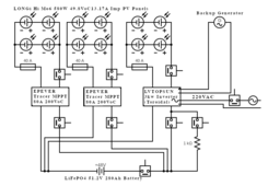
The schematic is not perfect due to limitations of the design software used, but imagine that each of the breakers for the PV arrays is connected to both positive and negative cables, i.e. a dual breaker. The fuses would just be on one line as shown.
One of my concerns with having parallel charge controllers like this is what might result if one charge controller failed, without its breaker being the issue (breaker remains closed). Would the current passing from the other controller and/or inverter cause problems in the reverse direction to the failed controller? Are there such things as diodes for this?
I have looked for something like a knife switch or a two-position switch by which the resistor could be connected at position 1 before the direct connection is made at position 2. Perhaps I do not know what search terms to use, but I have not found good options in this amperage range. In lieu of such a switch, I am considering having a second switch which must be manually engaged prior to closing the main switch. The problem with two switches is, of course, that it is less dummy proof: the resistor could be forgotten and not used, and the LF inverter's capacitors could draw a sudden high amperage.

As the diagram shows, the twelve PV panels would be in strings of two per string, with two strings per MPPT. Note that apparently LVTOPSUN inverters are made by Deye, which also apparently makes the Sol-Ark models sold in America. The battery comes with a JK BMS.
Being new to this, it is likely I am overlooking something, so I invite your critique. I haven't worked out yet how the CAN and/or RS485 connections should be made.
One of my concerns with having parallel charge controllers like this is what might result if one charge controller failed, without its breaker being the issue (breaker remains closed). Would the current passing from the other controller and/or inverter cause problems in the reverse direction to the failed controller? Are there such things as diodes for this?
I have looked for something like a knife switch or a two-position switch by which the resistor could be connected at position 1 before the direct connection is made at position 2. Perhaps I do not know what search terms to use, but I have not found good options in this amperage range. In lieu of such a switch, I am considering having a second switch which must be manually engaged prior to closing the main switch. The problem with two switches is, of course, that it is less dummy proof: the resistor could be forgotten and not used, and the LF inverter's capacitors could draw a sudden high amperage.

As the diagram shows, the twelve PV panels would be in strings of two per string, with two strings per MPPT. Note that apparently LVTOPSUN inverters are made by Deye, which also apparently makes the Sol-Ark models sold in America. The battery comes with a JK BMS.
Being new to this, it is likely I am overlooking something, so I invite your critique. I haven't worked out yet how the CAN and/or RS485 connections should be made.


